![[Introduction to Manufacturing Knowledge for IT Engineers, Part 1] What is a PLC (Programmable Logic Controller)?](https://images.ctfassets.net/ct0aopd36mqt/bmbvKrMGbl57z0F3Apaxw/b4a88c8ed2128b33cdfb1608f91463f7/bn_manufacturing.png?w=3840&fm=webp)
[Introduction to Manufacturing Knowledge for IT Engineers, Part 1] What is a PLC (Programmable Logic Controller)?

This page has been translated by machine translation. View original
This is Morinaga from Classmethod Malaysia.
Starting with this article, I will begin a series called "Introduction to Manufacturing Industry Knowledge for IT Engineers." When you become involved in projects with manufacturing customers, words unfamiliar in the IT industry — such as "PLC," "MES," and "BOM" — come up one after another in conversations with people on the shop floor. Without understanding their meanings, you may find it hard to follow conversations or correctly understand requirements.
In this series, I will take up terms commonly appearing in the manufacturing industry one by one and organize the key points that IT engineers should at minimum understand. The theme of the first installment is "PLC (Programmable Logic Controller)," an indispensable concept when discussing automation on the manufacturing floor.
What is a PLC?
A PLC is an industrial controller that automatically controls equipment such as motors, valves, and sensors on factory production lines and plants, according to a pre-written program. Its defining feature is that condition branching and timing control — such as moving a conveyor (output) when a button is pressed (input) — can be written and modified as software. Some people also call PLCs "sequencers," but they refer to the same thing.
Why They Were Born: Breaking Away from Relay Circuits
Before PLCs appeared, factory control was carried out by control panels combining large numbers of relays (electromagnetic contactors). While relay control is reliable in its operating principle, every time a production line's specifications changed, the physical wiring inside the control panel had to be rewired one wire at a time, and for large-scale facilities, this wiring change alone apparently required considerable effort and time.
PLCs were born as a solution to this challenge. According to this article and this article, the trigger was General Motors (GM) presenting a specification document called "Standard Machine Controller" to various vendors in 1968. The main requirements were as follows:
- Use solid-state elements (semiconductors) rather than relays, and be modular and expandable
- Be based on 16 inputs and 16 outputs, expandable up to 256 inputs and 128 outputs
- Handle specification changes through programming and reprogramming rather than rewiring
- Retain the program even during power outages
- Have a memory of at minimum 1k and at maximum 4k
The company that answered these specifications was Bedford Associates, which developed the "Modular Digital Controller." A concept memo was reportedly created in January 1968, and a prototype was demonstrated in March of the same year. This later became the "Modicon 084," and Bedford Associates changed its company name to Modicon in 1969. (It has since been acquired by Schneider Electric and become a PLC series name for that company.)
Another interesting point is the notation called "ladder diagram" used in PLC programming. The reason ladder diagrams look so similar to relay circuit diagrams is said to be because they were designed so that electrical technicians who were already familiar with electrical wiring diagrams at the time could transition to the new PLC without discomfort. However, the actual operating principle differs from relay circuits — a PLC achieves control by rapidly repeating a cycle (scan cycle) of "① read input states → ② execute the program sequentially from top to bottom → ③ update outputs." Unlike relay circuits, where multiple paths operate simultaneously, processing is carried out in an orderly sequence — a point that IT engineers may find intuitively easy to understand.
Let's look at what this actually looks like using a sample of the "self-holding circuit," a staple on the shop floor. It is a basic pattern commonly used when you want to maintain an operation not only while a button is being pressed, but also after it has been pressed.
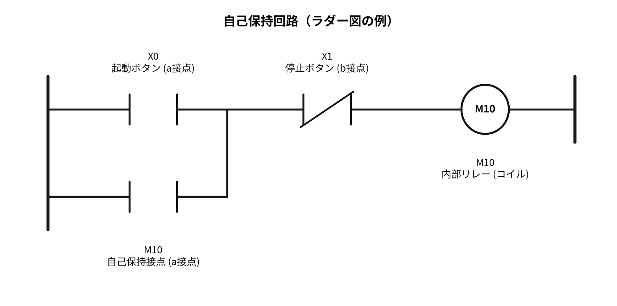
- Two vertical bars (
┤ ├): normally open contact (NO contact. A contact that turns ON when a button is pressed) - Two vertical bars with a diagonal line (
┤/├): normally closed contact (NC contact. A contact that is normally ON and turns OFF when a button is pressed) - Circle (
( )): coil (output)
In terms of operation, first pressing X0 (start button) turns M10 (internal relay) ON. When M10 turns ON, its own normally open contact (self-holding contact) also turns ON, so even when the X0 button is released, M10 remains in the ON state. To cancel this state, press X1 (stop button, NC contact). When X1 turns ON, the circuit is interrupted and M10 returns to OFF. The idea of "remembering that a button was pressed" rather than "reacting only at the moment of pressing" is close to what IT programming would call state management, and I think IT engineers will find it intuitively easy to understand.
Programming Methods Other Than Ladder Diagrams
When it comes to PLC programming, ladder diagrams are the first thing that comes to mind, but that is not all there is. PLC programming languages are standardized by an international standard called "IEC 61131-3," which defines the following five languages.
| Language | Type | Features |
|---|---|---|
| Ladder Diagram (LD) | Graphical | Notation resembling relay circuit diagrams. While ON/OFF control of bits is intuitively easy to understand, it tends to become harder to read as logic grows more complex |
| Function Block Diagram (FBD) | Graphical | Represents processing as a combination of blocks. The relationship between inputs and outputs is visually easy to understand |
| Sequential Function Chart (SFC) | Graphical | Well-suited for representing state transitions in a process; often used in combination with LD or ST rather than on its own |
| Structured Text (ST) | Text | Notation close to general-purpose programming languages, suited for writing complex calculations and logic |
| Instruction List (IL) | Text | A low-level list of instructions similar to assembly language |
Which language is used varies by manufacturer, tool, and target system, but it is worth knowing that "PLC = ladder diagrams only" is not the case — some sites use languages according to their purpose, such as ST for complex calculations and recipe management, or SFC for process state management.
PLCs Today: No Longer Limited to Being a Relay Replacement
So far, I have explained the origins of PLCs as a "replacement for relay circuits," but today's PLCs are no longer devices that only perform control. Functions were added to PLCs to temporarily store data collected from sensors and equipment on the shop floor, and to act as a bridge to higher-level systems via factory networks or the internet. The collected data can then be subjected to AI-based analysis on the server side and used for purposes such as visualizing operating status and detecting signs of failure (predictive maintenance).
In addition, in recent years, an increasing number of PLCs support cloud connectivity and take on the role of "edge computing," running containerized applications to perform data preprocessing and machine learning inference.
In other words, today's PLCs are expected to serve not only as "controllers that perform control," but also as "entry points (edges) for bringing shop floor data into the IT side." If IT engineers have opportunities to work with PLCs, it is often in the context of such data collection and integration.
You Can Try PLC Programming Without Real Hardware
For those who want to try building a ladder diagram themselves, here are two tools that let you experience PLC programming with just a PC, even without actual PLC hardware.
- OpenPLC: Free, open-source PLC software. "OpenPLC Editor," the tool for writing programs, runs on Windows/Linux/macOS and supports ladder diagrams, ST, FBD, and SFC. Even without real hardware, you can run the programs you create and verify their operation using only software on your PC. You can also connect a Raspberry Pi and operate hardware.
- CODESYS: A development environment compliant with IEC 61131-3, provided by CODESYS of Germany, that is not tied to any specific PLC manufacturer. The development environment (CODESYS Development System) is available as a free download. It also includes a feature for running control programs in a virtual environment, which can be used for learning and verification without real hardware.
Both are tools you can try on the principle of "learn by doing," so even if you don't have opportunities to directly work with real PLCs on the shop floor, actually getting your hands on them to feel what PLC programming is like should deepen your understanding.
The Position of PLCs in ISA-95
The term "ISA-95" also comes up frequently in manufacturing conversations. ISA-95 (IEC 62264 as an international standard) is a reference model that organizes the various systems within a factory into levels 0 through 4 according to the roles they perform. Since this is a concept that will appear repeatedly in this series, I will briefly introduce it here.
| Level | Main Role | Examples of Applicable Systems |
|---|---|---|
| Level 4 | Business planning and core operations | ERP, supply chain management |
| Level 3 | Manufacturing operations management | MES (Manufacturing Execution System) |
| Level 2 | Monitoring and control | PLC, DCS, SCADA |
| Level 1 | Sensing and operation | Sensors, actuators, I/O modules |
| Level 0 | The physical process itself | Actual production equipment and machinery |
※ Depending on the reference material, PLCs may sometimes be positioned at Level 1 (sensing and operation). See the body text following the table for supplementary details.
Some references, such as this explanation, clearly position PLCs at Level 2 (the monitoring and control layer). On the other hand, PLCs themselves often handle sensors and actuators directly through I/O (taking on a role corresponding to Level 1 as well), and the reality is that the representation varies across reference materials. Therefore, in this article, I will limit our understanding to the position that PLCs are located somewhere around Levels 1 to 2.
Note that the "Purdue Model," which often comes up in the context of security, is also frequently discussed using levels 0 through 4 like ISA-95, but its purpose is different. The Purdue Model is a model focused on network segmentation and security zone design, while ISA-95 is a model for organizing data integration between enterprise systems and control systems.
Major PLC Manufacturers in Japan and Overseas
Here are PLC manufacturers whose names frequently come up on the shop floor, organized into domestic and overseas categories. Please refer to each company's official product pages for details.
Domestic Manufacturers
- Mitsubishi Electric: Offers the MELSEC iQ-R series, MELSEC-Q/L/FX series, and others. (Product page)
- OMRON: Offers the Sysmac NJ/NX series and others under the integrated automation platform "Sysmac." (Product page)
- KEYENCE: Offers the KV-8000/7000 series, KV-Nano series, and others. (Product page)
Overseas Manufacturers
- Siemens (Germany): Offers the SIMATIC S7-1500/1200 series and others, compatible with the integrated development environment "TIA Portal." (Product page)
- Rockwell Automation (United States): Offers the EtherNet/IP-compatible ControlLogix and CompactLogix series and others under the Allen-Bradley brand. (Product page)
- Schneider Electric (France): Offers the Modicon series and others, integrated with the IoT platform "EcoStruxure." (Product page)
Things IT Engineers Should Know
Finally, from the perspective of an IT engineer involved in manufacturing projects, here are some points that may be useful to keep in mind regarding PLCs.
- Program changes often involve shutting down shop floor equipment: Unlike web systems where deployment can be done casually, changes generally require stopping shop floor operations, confirming safety, and coordinating on-site work.
- Communication protocols are diverse: PLCs have historically used proprietary protocols specific to each manufacturer, and today multiple standards — including EtherNet/IP, PROFINET, Modbus, and OPC UA — coexist. When connecting IT-side systems to PLCs, it is necessary to confirm which protocol will be used to retrieve data.
- Cultural differences between OT (Operational Technology) and IT: The world of control systems including PLCs has a strong culture of "safety first, availability is the top priority," where keeping things running is prioritized over confidentiality.
Summary
In this first installment of "Introduction to Manufacturing Industry Knowledge for IT Engineers," I introduced the basic role of PLCs, the background of their creation, their positioning in ISA-95, major manufacturers, and the key points IT engineers should keep in mind.
While PLCs are a central element supporting manufacturing automation, they tend to be a black box for people from the IT industry. Simply getting hands-on experience with PLC programming through tools like OpenPLC or CODESYS should advance your understanding a little.