![[Summer Vacation Free Research Relay] Can Even Someone Who Has No CAD Skills Whatsoever Create Shapes Freely with a 3D Printer and AI?](https://devio2024-media.developers.io/image/upload/f_auto,q_auto,w_3840/v1786434555/user-gen-eyecatch/hpk1uqel2qnvssyhrk8q.png)
[Summer Vacation Free Research Relay] Can Even Someone Who Has No CAD Skills Whatsoever Create Shapes Freely with a 3D Printer and AI?

This page has been translated by machine translation. View original
Hello, I'm watabo from Classmethod Operations.
This article is the 14th entry in the 'Summer Vacation Independent Research Relay' by Classmethod volunteers.
This blog relay project is an initiative by members who regularly follow cloud and AI to output not just "tried it" but also "built it" and "researched/studied it."
Just recently, I got my hands on a 3D printer (Bambu Lab A1 mini).
It's an inexpensive yet wonderfully high-quality 3D printer.
Models created by other users are publicly available through the dedicated software Bambu Studio / Maker World, so even without CAD skills you can download and print them for fun.
However, as you use it, the desire naturally arises to create parts and small everyday items exactly the way you want...
I have no experience with CAD software, and honestly learning modeling from scratch sounds exhausting.
So this time, I tried an approach where "I only measure the dimensions myself, and leave the modeling and rendering verification to Claude Code."
Specifically, I had Claude Code write OpenSCAD (a 3D CAD tool that models with code) code, have Claude itself verify the rendered images (png), and if there are problems, fix them on its own — running this loop autonomously.
All the human does is measure dimensions with a caliper and report how the printed fit feels.
This entry covers the whole story from environment setup, through tolerance calibration, to completing a bag hook to attach to a desk.
Environment
| Item | Details |
|---|---|
| Printer | Bambu Lab A1 mini (build size 180×180×180mm, open frame) |
| Filament | PETG |
| Slicer | Bambu Studio |
| OpenSCAD | Nightly build 2026.06.12 |
| Development Environment | Claude Code (Pro plan) |
I happened to only have PETG filament on hand, so I used that, but regular PLA should be fine too.
Current State of AI × 3D Printing
No matter how advanced AI has become, I wondered if this was really feasible — and if it were, there should already be plenty of blog posts about it, so I did some research.
As of August 2026, there seem to be two main routes for combining 3D printing with AI.
| Route | Good at | Not good at |
|---|---|---|
| Mesh generation (Meshy, Tripo, etc.) | Appearance-focused modeling like figurines and decorative items | Dimensional accuracy, fine-tuning after the fact |
| Code generation (OpenSCAD × LLM) | Dimensional accuracy based on measured values, re-adjustment through variable parameterization | Complex organic shapes |
Mesh generation already seems to have quite a few blog posts.
Bambu Lab itself also offers a service called Maker Lab.
However, since I wanted to create something reasonably practical this time, I chose the code generation approach with OpenSCAD.
OpenSCAD is a tool that describes all shapes in code (variables and formulas), so the advantage is that you can adjust dimensions after the fact by changing a single variable.
Setup and Environment Construction
The intended workflow was as follows:
- The human measures dimensions with a caliper and communicates the specifications to Claude Code
- Claude Code writes the
.scadfile - Render a preview image using the
openscadCLI - Claude Code loads the rendered image itself and visually checks the shape
- If there are problems, it fixes them without asking the human and returns to step 3
- Once converged, output the STL
- The human prints it and reports the fit result
Since Claude Code can load images (multimodal), it can visually check what shape the code it wrote produced, and if it differs from the intent, it can fix it on its own.
The human was not expected to open CAD at all.
Installing OpenSCAD Nightly Build
OpenSCAD has a mature stable release (2021.01) and a Nightly build that does daily builds of the latest development code.
I chose the Nightly build because the stable version is far too old, and because the Manifold backend makes rendering faster.
openscad --version
# OpenSCAD version 2026.06.12
Test ① Understanding Printer Tendencies with Tolerance Test Pieces
A 3D printer doesn't necessarily output at exactly the designed dimensions.
Holes in particular tend to come out smaller than the design value, because the melted resin sags slightly.
If you design parts without understanding this "shrinkage amount," you'll end up in a situation where screws or cables won't fit into the holes.
So first, I had Claude Code create a calibration test piece with hole diameters from 4.6 to 5.2mm in 0.1mm increments.
The diameter value is engraved below each hole.
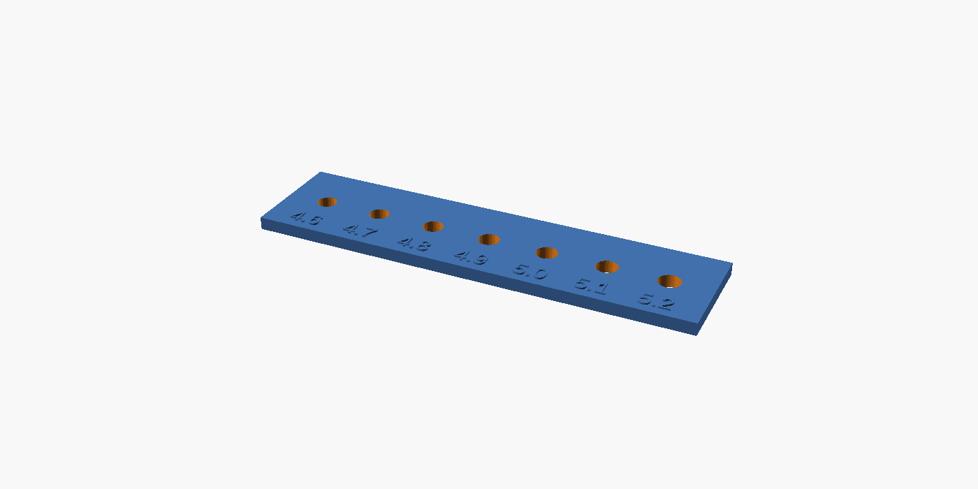
This model achieved the intended shape after a single rendering check and was sent straight to printing.
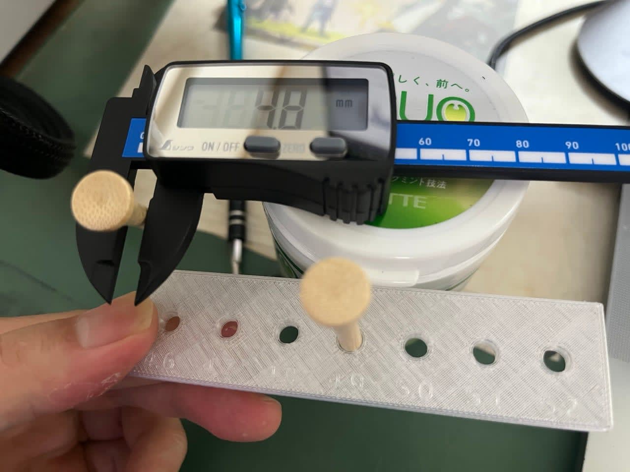
I inserted a round rod with an actual measured diameter of 4.8mm (a bamboo golf tee I happened to have at home) into the printed test piece to check the fit.
Measuring the printed results revealed the following:
- A rod with an actual measurement of 4.8mm does not fit into the nominal 4.9mm hole
- It just barely press-fits into the nominal 5.0mm hole
In other words, with this printer (Bambu Lab A1 mini, PETG), hole diameters tend to come out approximately 0.2mm smaller than the nominal value.
Based on this result, I set the initial value of the clearance adjustment variable (designed so that hole diameter = target diameter + clearance × 2) to 0.2mm.
Test ② Designing the Bag Hook
With calibration complete, I moved on to the main component.
I was thinking about what to make, and then remembered that one of the built-in hooks on a wooden shelf had broken recently, so I decided to make a replacement.
It's a hook that screws into the side and is used for hanging bags and similar items.
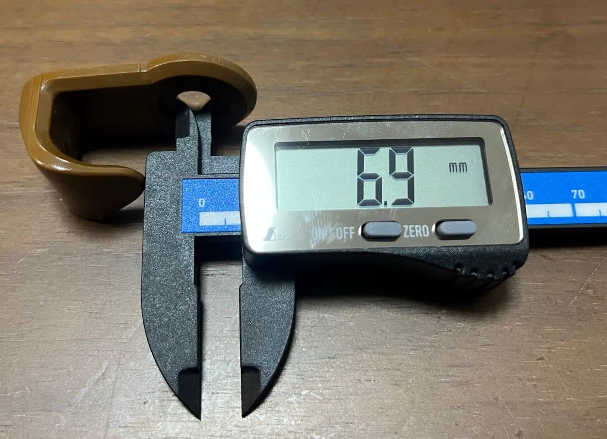
Here's what the actual thing looks like.
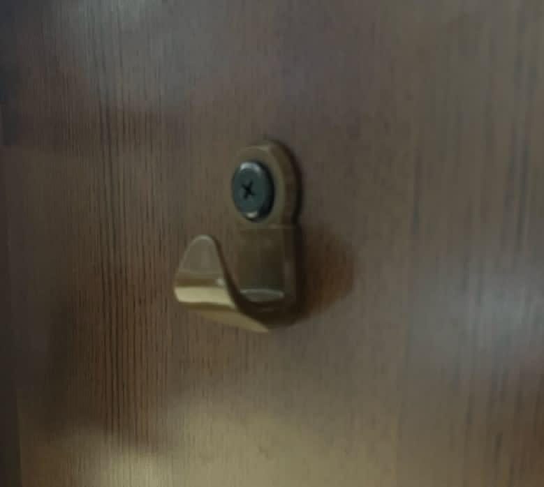
Here's what it looks like removed from where it was screwed in.
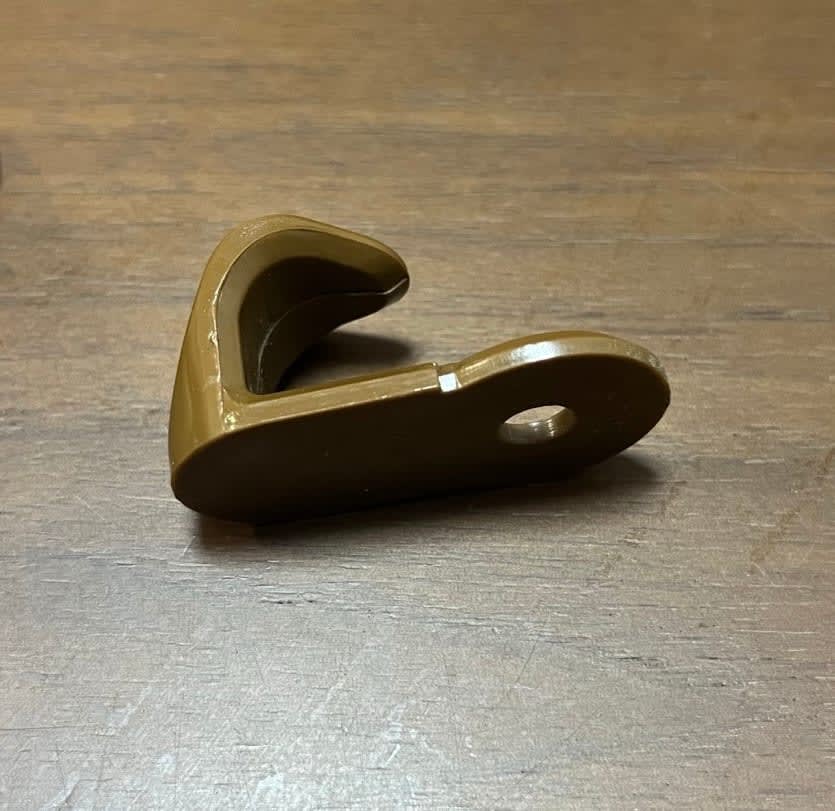
First Design Attempt
Now, I needed to convey this shape to Claude, but I had absolutely no idea how to describe the part shape.
My vocabulary was just too limited — how do you describe this as anything other than "it's a hook"?!
I didn't even know what to call each part.
As mentioned earlier, I had the actual existing part, so I just took several photos and sent them.
The screw holes were something I really needed to communicate properly, so I measured those with a caliper.
Sonnet 5, can you make something of this...?
Here's what Claude produced after operating OpenSCAD and rendering it.
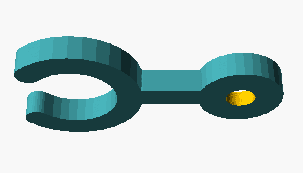
What came out looked nothing like the original hook.
I tried giving correction instructions several times, but it was hopeless, so I scrapped the entire session.
I felt grateful that being able to see the preview before printing saved me from wasting a print.
Redesign
The shape isn't that complex to begin with, and I didn't want to make a perfect copy of the existing hook, so I tried passing just one image and then working out the requirements afterward.
The response came back with quite a few reverse questions, which made me reflect that yes, the shape really does change significantly depending on where you're mounting it...
【Part name】
【Measured values】(confirmed values measured with caliper. What did the 6.9mm you mentioned measure?)
【Desired values】(preferences for overall size and shape)
【Mounting method】(how it hooks/attaches to what)
【Material】(PETG assumed, is that correct?)
【Print orientation】
【Notes】(positioning of the tan-colored part, etc.)

What I especially want to know:
1. What is the hook for hanging? (e.g., bag, cable, towel, etc.)
2. Where does it mount? (e.g., shelf edge, desk top, wall, etc.) → Need actual measurements of mounting surface thickness and shape
3. Is the tan-colored part in the photo a reference for "I want something shaped like this," or is it part of what it hooks onto?
After various exchanges, here's what it first produced.
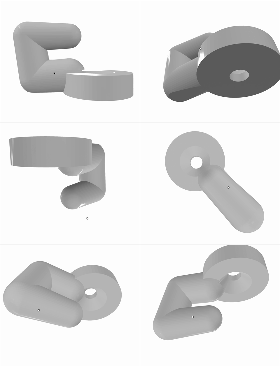
The arm part is way too beefy — it looks like once you hang a bag on it, it would be hard to take off.
However, it got considerably closer to the shape I had in mind.
I also noticed the following issues and gave feedback to have it reworked:
- Printing with the back plate as the bed surface would leave it floating in the air, requiring supports, which would result in a poor print
- → Rotate 90 degrees for printing
- Changing the print orientation meant it wouldn't stand on its own when laid on its side
- → Make the boss and arm share the same plane
Ultimately it settled into the following shape. This should be attachable as-is.
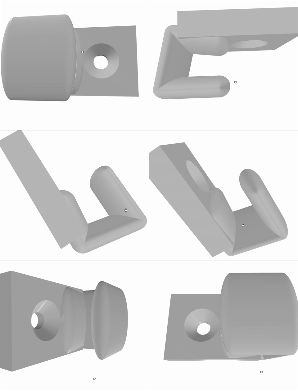
Printing It
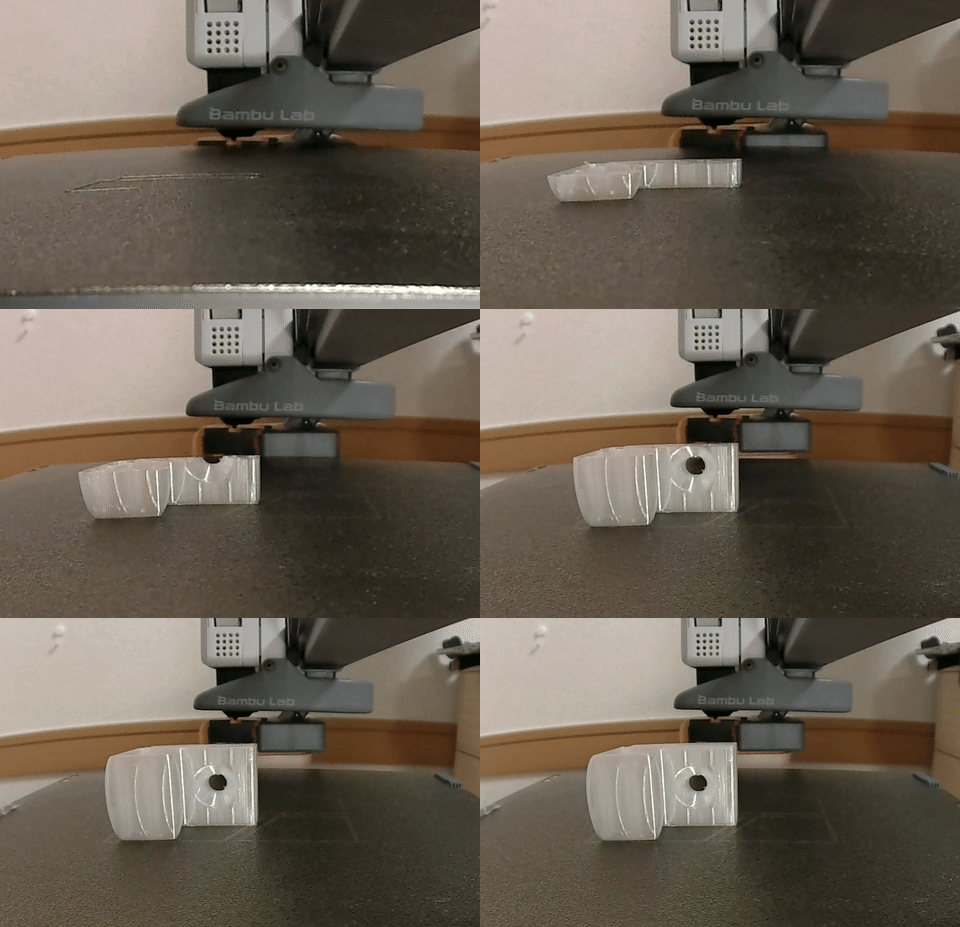
I printed the STL created on the A1 mini.
It took about 30 minutes.
(No matter how many times I watch this timelapse, it looks terrifyingly like something is being created from nothing)
The printing itself completed without issues, so I immediately tried to attach it — but the screw wouldn't go into the hole!!!
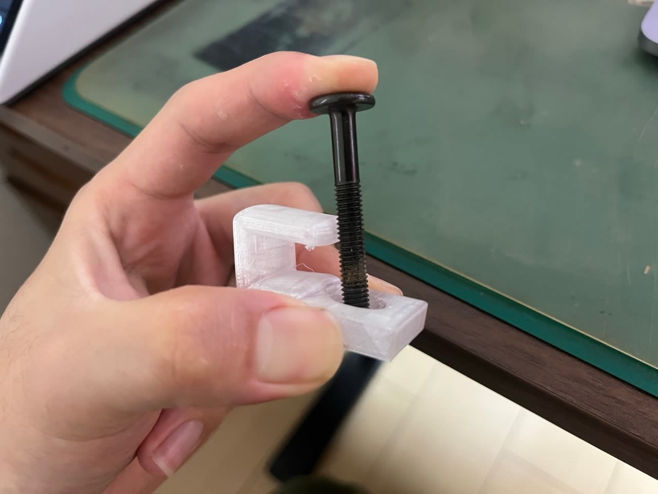
The likely cause was that changing the print orientation had changed the screw hole direction from vertical → horizontal.
The calibration from the tolerance test piece (clearance = 0.2) was the value for printing holes vertically (perpendicular to the layer direction).
As a result of laying the part on its side for printing, the hole axis became horizontal (parallel to the layer direction).
Horizontal holes generally tend to sag slightly at the top due to the layer structure, meaning the same clearance as vertical holes may not be sufficient.
Incidentally, even after reprinting it still wouldn't fit, so it might be a good idea to use a slightly larger clearance to be safe.
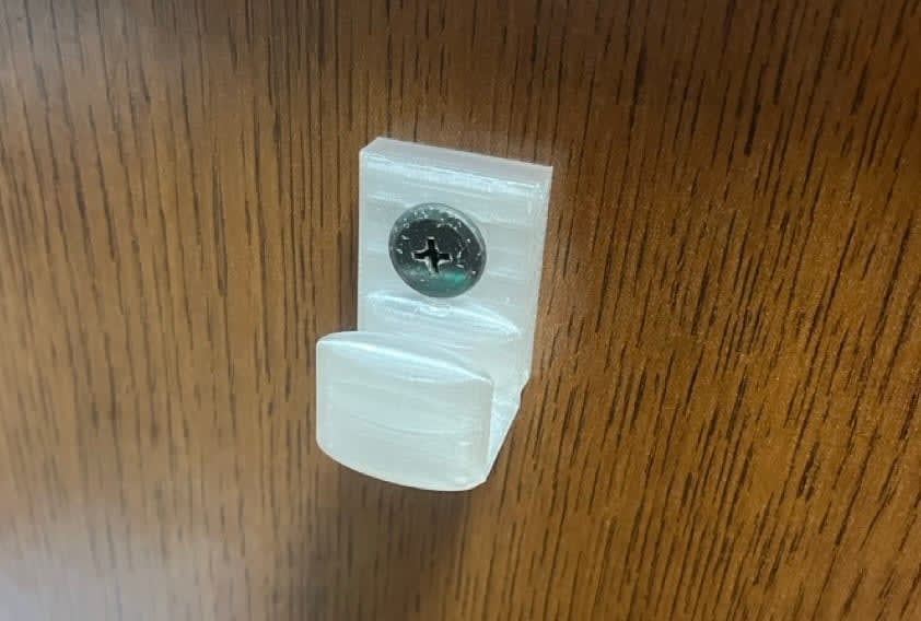
In the end, I drilled the holes out and was able to attach it. The strength seems fine for now.
I probably could have at least matched the color.
Results and Observations
What I Learned
- Holes come out smaller than the nominal value (in this environment, about 0.2mm for vertical holes).
- Building
clearanceas a variable into the design lets you adjust by back-calculating from print results
- Building
- Even with the same
clearancevalue, vertical and horizontal holes may finish differently.- It seems better to verify the orientation of each hole at the same time as deciding the print orientation
- Claude Code can notice on its own that a rendered image "differs from the intent" and make corrections, but if the initial requirements don't convey the dimensions and purpose properly, things go increasingly off track
- (This is similar to coding, isn't it?)
What the Human Did
- Actual measurements with a caliper (screw hole specs of reference part, bag handle dimensions, rod diameter of printed result)
- Executing the prints
- Providing feedback based on printed results ("the arm is too beefy," "worried about strength," "it floats and can't print properly," "the hole looks off-center," "the screw won't go in")
All CAD operations, dimension calculations, and code writing were handled entirely by Claude Code.
Closing
I found that even without CAD knowledge, just by passing measured values and running a loop of checking rendered images, it's possible to somehow arrive at a practical part with correct dimensions.
Along the way, there were multiple stumbling points including the instructions to Claude and the print orientation issue, but in each case Claude Code either noticed by looking at the rendered image or fixed things on its own after receiving feedback.
On the other hand, the insight that vertical and horizontal holes require different clearances was the kind of knowledge you can only gain by actually printing and failing.
That makes sense in hindsight, but it really is something you can't know until you print.
I also genuinely found it difficult to create CAD data using just natural language and images. Without background knowledge, you really can't do it freely.
Maybe I should just learn CAD after all...
I hope this entry is helpful to someone.
References
Bonus
Here is the CLAUDE.md used for this project.
CLAUDE.md
# AI × 3D Printer: OpenSCAD Autonomous Modeling Project

## Project Purpose

Without using CAD, have Claude Code autonomously run the loop of OpenSCAD code generation → rendering verification → correction,
and complete an STL for a practical part printable on the Bambu Lab A1 mini.
The human's role is only to "provide dimension specifications" and "print and report fit results."

## Environment / Prerequisites

- Printer: Bambu Lab A1 mini (build size 180×180×180mm, open frame)
- Filament: PLA as default. PETG for outdoor/heat-resistant applications
  - Note: Only PETG was available, so proceed on that assumption
- Slicer: Bambu Studio (reads STL directly)
- OpenSCAD: Nightly build, with CLI in PATH
  - Verification: `openscad --version`

## Workflow (Run this loop autonomously)

1. Receive dimension specifications (format below)
2. Write the `.scad` file
3. Render a preview
   `openscad -o preview.png --imgsize=1024,1024 <part>.scad`
4. **Read the generated preview.png yourself and visually verify the shape**
   - Verification points: Is it the intended shape / position of holes and grooves / are wall thicknesses not too thin (minimum 1.6mm guideline) / is the bed contact surface flat
   - If needed, render multiple images from different camera angles (`--camera` option)
5. If there are problems, return to step 2 (fix without asking the human)
6. Once converged, output the STL
   `openscad -o <part>.stl <part>.scad`
7. The human will print and report fit results, so adjust variables and re-output as needed

## Dimension Specification Format (Input from Human)

【Part name】Cable clip
【Measured values】Cable diameter 4.8mm / Desktop thickness 24.6mm
【Desired values】Total width approximately 20mm (some variation acceptable)
【Mounting method】Clamp to desktop
【Material】PLA
【Print orientation】Bottom face on bed
【Notes】...

- "Measured values" = confirmed values measured with caliper. Do not round arbitrarily
- "Desired values" = guideline. May be changed for design reasons, but report any changes
- If a hand-drawn sketch image is provided, list out the dimensions you've read before implementing and confirm with the user

## Coding Conventions (OpenSCAD)

- Units are mm (slicer interprets 1 unit = 1mm)
- **Parameterize all dimensions** and collect them at the top of the file. No magic numbers
- All fit/mating areas must have a `clearance` variable. Default value 0.2

  clearance = 0.2;        // Fit adjustment. If tight, add +0.1
  cable_d   = 4.8;        // Measured value
  hole_d    = cable_d + clearance * 2;

- `$fn` is 32 during development, 64 or more for STL output
- 1 part = 1 file. File names in lowercase snake_case (e.g., `cable_clip.scad`)
- Comments may be in Japanese. Note the source of measured values (e.g., `// USB-C cable measured`)

## Design Rules Considering Printing

- Clearly define the bed contact surface and design so that surface is flat
- Overhangs exceeding 45° require supports; first consider whether chamfering can avoid this
- Horizontal holes sag at the top if perfectly round; consider teardrop shape if precision is needed
- Wall thickness minimum 1.6mm (0.4mm nozzle × 4 perimeters). 2.4mm or more for load-bearing parts
- Must not exceed build size of 180mm

## First Tasks

1. **Tolerance test piece**: Create a plate with holes from 4.6 to 5.2mm in 0.1mm increments (with diameter engraved below each hole)
   → Understand this printer's shrinkage tendency from print results and calibrate the initial `clearance` value
2. After calibration, begin the main part

## Output Management

- `parts/<part>.scad` … Source
- `stl/<part>.stl` … Output
- `preview/<part>_*.png` … Rendered images
That concludes the 14th entry in the 'Summer Vacation Independent Research Relay': 'Can Someone with Zero CAD Skills Model Freely with a 3D Printer and AI?'
The next entry will be Morio-san's "I Implemented All of Claude Team, ChatGPT Business, and Gemini Enterprise Business." Look forward to it!!