![[Summer Vacation Free Research Relay] Visualizing Claude Code Processing Status with ESP32](https://devio2024-media.developers.io/image/upload/f_auto,q_auto,w_3840/v1788175460/user-gen-eyecatch/yrxy1heipheejwcysrr3.jpg)
[Summer Vacation Free Research Relay] Visualizing Claude Code Processing Status with ESP32

This page has been translated by machine translation. View original
Introduction
Hello everyone, this is Akaike.
This article is the 28th entry in Classmethod's volunteer-driven "Summer Vacation Free Research Relay."
This blog relay project is organized by members who regularly follow cloud and AI, with the goal of outputting not only "tried it" but also "built it" and "researched/studied it."
We hope this will provide new insights and contribute ideas to the development of our company and community, so we appreciate your continued reading.
Motivation
I've been doing various things to visualize Claude Code's processing status.
Specifically, I tried spinning a mirror ball, but there were the following disadvantages that prevented it from being used in actual work.
- Mirror balls aren't available everywhere
- There are situations where using a mirror ball is inappropriate given the context
- You need to bring a mirror ball to the office
So this time, using an ESP32, I made it cuter, more compact, and more convenient to
visualize Claude Code's processing status.
For basic ESP32 setup and usage, I've written the following blog post, so please refer to it if you're interested.
What I Built
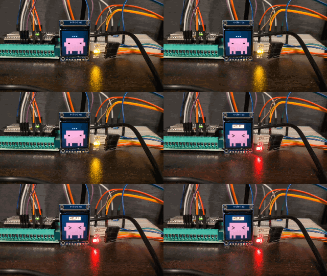
It works in sync with Claude Code's processing status like this.
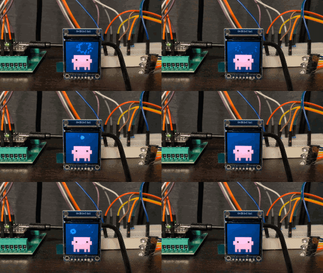
- Session startup motion
- It wakes up together with Claude Code's session start
- Processing motion
- When you throw a prompt, Thinking time begins
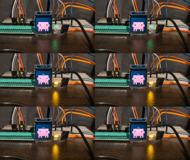
- Waiting for approval motion
- It asks for help when user approval is needed
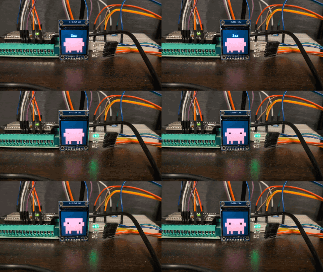
- Session end motion
- After finishing a job, it goes to sleep — good work!
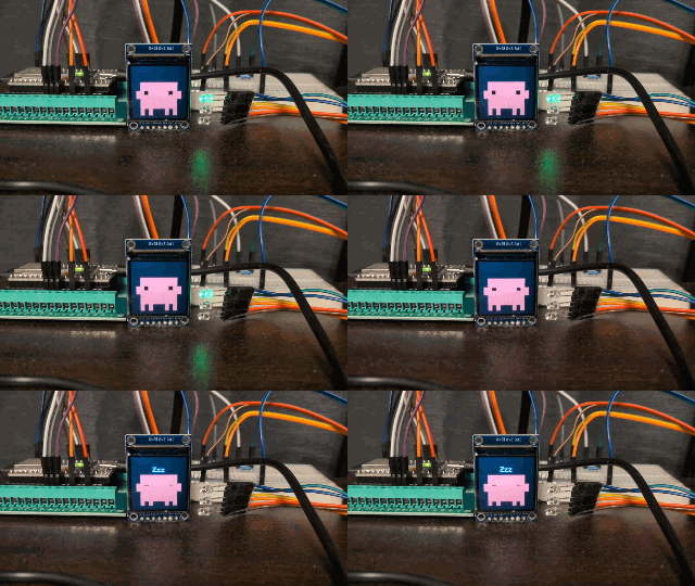
Cute, isn't it.
Defining What I Want to Do
Based on the lessons learned from the mirror ball, this time I aimed to satisfy the following three criteria.
- Visualize it in a cute way
- Since it's something I'll be looking at every day, it's more fun to have a mascot moving around than a plain mirror ball
- Make it easy to see at a glance
- I want to be able to tell the current state at a glance from a distance or from the side
- Do it on a low budget
- With an eye toward spreading it to Claude users across the country, I want to keep the cost to a few thousand yen including peripheral parts
Architecture
Here's an overview of the whole thing.
Claude Code's hook writes the state to a file, a resident process monitors that file and sends it to the ESP32 via serial communication, and the ESP32 side converts it into animations and LED signals.
I think it might be hard to follow, so I'll explain the details from here.
Let's Implement It
The full code is available below, so please feel free to use it.
In this blog, I'll pick out the key points and explain them.
What You'll Need
Here's what I used.
Note that for the hardware, it should work even if you don't use the exact same products, so this is just one example.
- Software
- Claude account (any plan)
- Hardware
- ESP32 (FNK0090B)
- 1,390 yen
- USB cable (the one that came with the ESP32)
- 0 yen
- Breakout board for ESP32
- 700 yen
- Breadboard (for LED)
- 200 yen
- Jumper wire set (arduino wire gauge 28AWG)
- 800 yen for 120, used 17 = approx. 113 yen
- Single-color LEDs × 3 (green / orange / red)
- 800 yen for 200, used 3 = 12 yen
- Resistors × 3 (use resistors that are appropriate for your LEDs)
- 1,000 yen for 1,280, used 3 = approx. 2 yen
- 1.3-inch IPS LCD (ST7789VW, SPI connection, 240×240px)
- 1,200 yen
- ESP32 (FNK0090B)
So the total came to around 3,617 yen.
I bought most of it on Amazon, so it might be a bit cheaper if you buy from specialty stores.
Hardware
About Wiring
Instead of plugging jumper wires directly into the ESP32, I used a breakout board.
The pin layout of the ESP32 I used this time is as follows.
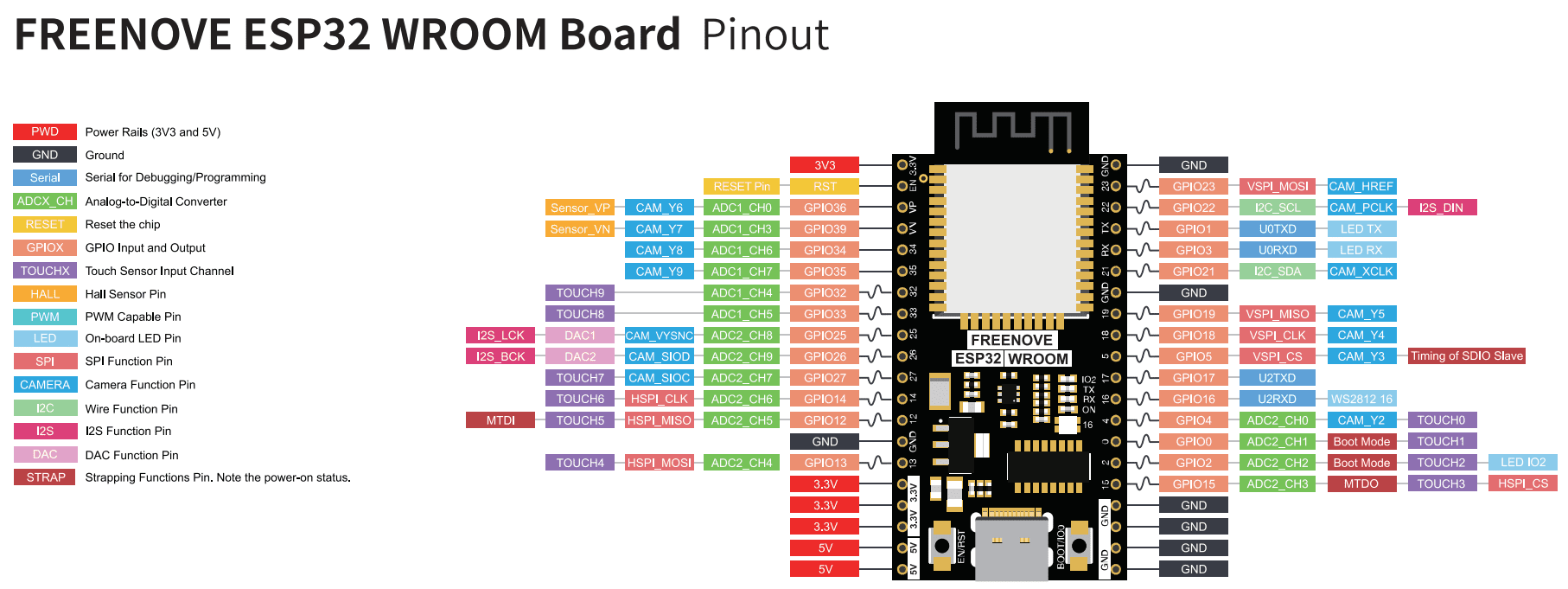
I extended jumper wires from the breakout board's pin headers, connected the LEDs and resistors to a separate breadboard, and connected the LCD module with its dedicated cable.
The correspondence between the LCD and the 3 LEDs is as follows.
| Purpose | ESP32 side | Connected to |
|---|---|---|
| LCD Power | 3.3V | VIN |
| LCD GND | GND | GND |
| LCD MOSI | GPIO23 | SDA |
| LCD SCK | GPIO18 | SCL |
| LCD RES | GPIO17 | RES |
| LCD DC | GPIO16 | DC |
| LCD Backlight | GPIO4 | BLK |
| LED0 | GPIO25 | Green (via resistor to GND) |
| LED1 | GPIO26 | Orange (via resistor to GND) |
| LED2 | GPIO27 | Red (via resistor to GND) |
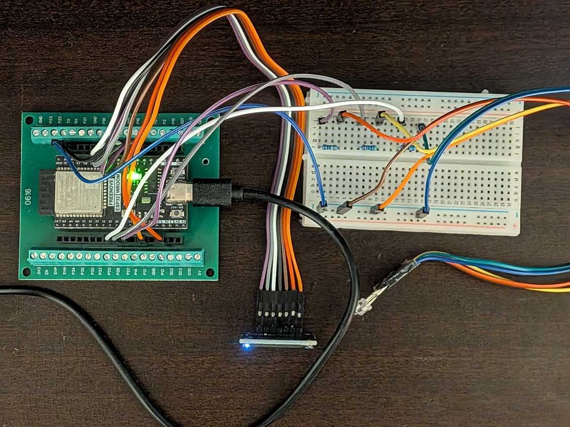
Here's what the actual wiring looks like from above.
About the LEDs
The LEDs are connected to GPIOs through resistors, and the colors are the same as traffic lights: green, yellow, and red.
Green for standby, yellow for processing, red for waiting for approval, and so on.
Also, instead of blinking or fading, they are expressed only as always-on and off.
static const int LED_PINS[] = {25, 26, 27};  // Green / Orange / Red

void updateLeds(State s) {
  bool green = false, yellow = false, red = false;
  switch (s) {
    case ST_IDLE:       green = true;  break;
    case ST_PROCESSING: yellow = true; break;
    case ST_APPROVAL:   red = true;    break;
  }
  setLed(0, green  ? 255 : 0);
  setLed(1, yellow ? 255 : 0);
  setLed(2, red    ? 255 : 0);
}
About the Monitor
The LCD module I used this time did not come with pin headers, so soldering was required beforehand.
The wiring itself is as described in the wiring table above.
This clone had an individual difference where it wouldn't display unless SPI_MODE3 was specified during ST7789 initialization.
tft.init(TFT_WIDTH, TFT_HEIGHT, SPI_MODE3);
If the screen stays completely black and nothing is displayed, try changing it to SPI_MODE0.
Software
About the Communication Method
On development boards like the ESP32, the act of opening a USB serial port itself triggers an automatic reset of the board.
If the port is opened and closed every time a hook fires, the ESP32 restarts each time and the animation stops.
So I prepared a resident process (bridge) in Python that keeps the serial port open at all times.
All the hook needs to do is write the state as a single word to a file.
# set-state.sh (called from hook)
echo "$1" > "$RUN/led.state"
The bridge side simply polls this file and streams it to serial whenever there's a change.
# bridge.py (resident process, excerpt)
while True:
    led = read_text(LED_FILE)
    if led and led != last_led:
        send(f"STATE {led}")
        last_led = led
    time.sleep(POLL)
The reason the hook only does file writing is that having the hook itself perform time-consuming processing like serial communication would slow down Claude Code's responses.
The actual bridge.py also includes processing to automatically reconnect when the serial connection drops due to plugging/unplugging the ESP32, and processing to finish sending the final state (OFF) before exiting when the session ends, but these are simplified here for explanation purposes.
The ESP32 side simply looks up the received word in this lookup table and switches states.
static const CommandAlias COMMAND_ALIASES[] = {
  {"START", ST_START},
  {"IDLE",  ST_IDLE},
  {"BUSY",  ST_PROCESSING},
  {"WAIT",  ST_APPROVAL},
  {"OFF",   ST_END},
};
About Clawd's Drawing Method
If you transfer directly to the LCD every time you draw, you'll see flickering as the transfer is in progress.
So I draw one full frame to Adafruit GFX library's offscreen canvas (GFXcanvas16) first, then transfer the completed image to the LCD all at once.
void drawClawd(const Pose &p) {
  canvas.fillScreen(COLOR_BG);
  fillO(O_TORSO_X, O_TORSO_Y, O_TORSO_W, O_TORSO_H, 0, p.body);  // torso
  // ...legs and eyes are also drawn to canvas in the same way
  tft.drawRGBBitmap(CANVAS_X, CANVAS_Y, canvas.getBuffer(), CANVAS_W, CANVAS_H);  // bulk transfer here
}
The pose is calculated by feeding the elapsed time since entering a state into a sine wave.
// IDLE: move up and down slowly like breathing
p.jumpY = -(int)(2 * (1 + sinf(t * 2 * M_PI / 3.0f)));
By simply changing the period and amplitude — breathing for standby, walking for processing, trembling for waiting for approval — each motion is expressed.
About Claude Code Settings
Claude Code's hooks are simply a mechanism that calls a command at a defined timing.
For example, when it enters the waiting-for-approval state, it is registered like this.
"PermissionRequest": [
  {
    "hooks": [
      { "type": "command", "command": "$CLAUDE_PROJECT_DIR/.claude/esp32/set-state.sh WAIT" }
    ]
  }
]
Here is the full picture of the hooks registered in .claude/settings.json.
| Timing (hook) | State written |
|---|---|
| Session start (SessionStart) | Wake up |
| Prompt submission (UserPromptSubmit) | Processing |
| The moment a tool requires approval (PermissionRequest) | Waiting for approval |
| After tool execution (PostToolUse) | Processing |
| Response complete (Stop) | Standby |
| Session end (SessionEnd) | End |
Note that only SessionStart and SessionEnd also serve to start and stop the bridge itself, in addition to simply writing the state.
Future Challenges
It's in a working state for now, but the following challenges remain for everyday use.
These are things I'd like to improve together with Claude going forward.
- There is no hook to detect when "Deny" is selected in the approval dialog, so the waiting-for-approval screen remains immediately after denying
- Since it returns to the normal processing display when you send the next prompt, I'll accept this for now (compromise)
- The board is exposed
- Move from breadboard to printed circuit board
- Create a body with a 3D printer or similar
- Can only handle one Claude Code session
- Use a larger monitor and control screen splitting
- Switch from serial port to HTTP
Conclusion
That's a wrap on the 28th entry of the "Summer Vacation Free Research Relay."
Just like with the mirror ball, I jumped into this on impulse, but I'm satisfied with how it turned out in a cute way.
If you ever want to visualize Claude Code's processing status in a cute way, give it a try.
The end of summer with Claude — dreams for the future, great hopes, I won't forget
Believing we'll meet again next August
The best memories...