I tried assembling the SO-ARM101 and doing teleoperation with LeRobot

This page has been translated by machine translation. View original
Introduction
Hello, I'm Morishige from Classmethod's Manufacturing Business Technology Department.
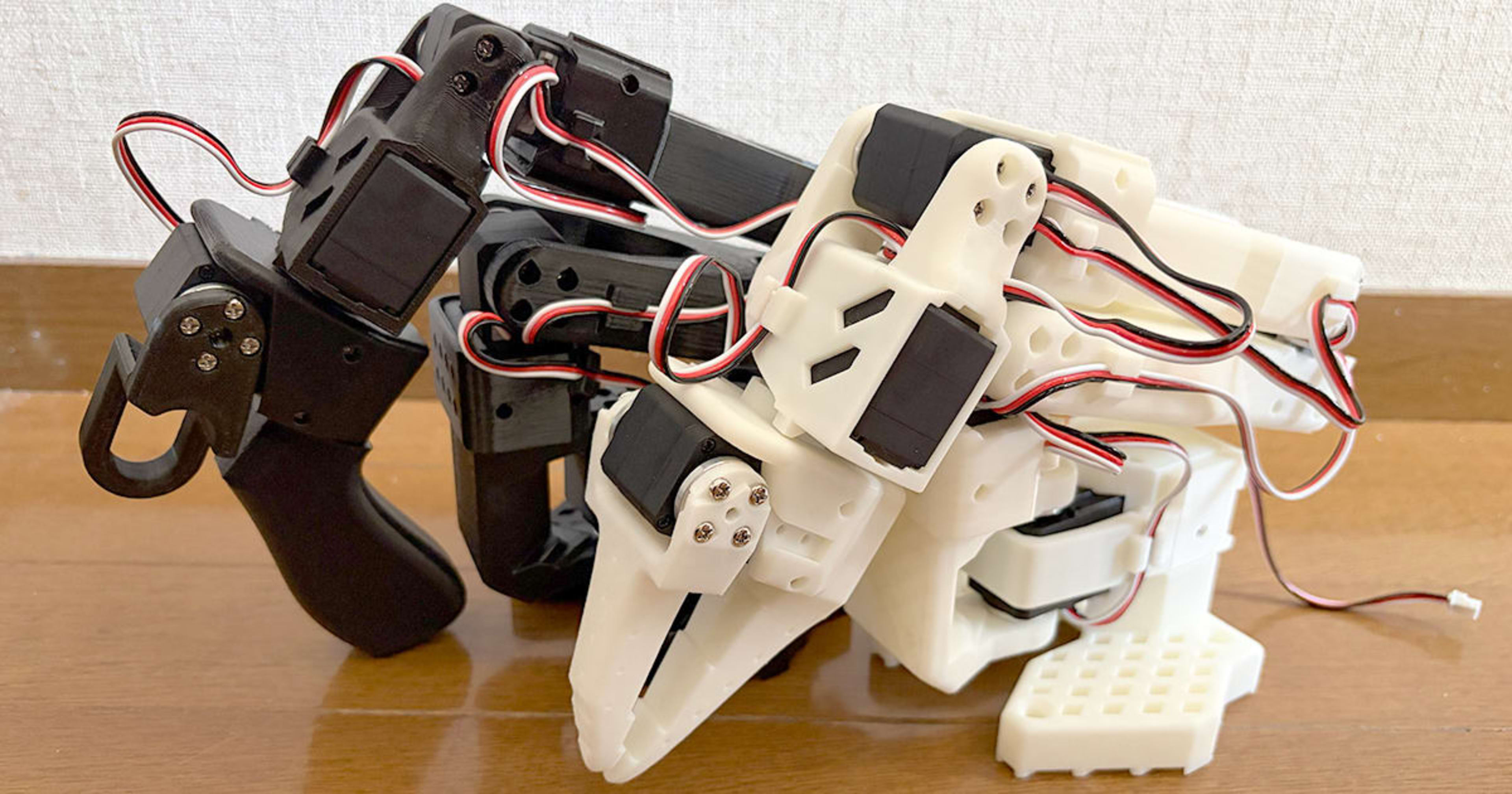
In a previous article, I worked on reinforcement learning for the SO-ARM101 in Isaac Sim's simulation environment and observed how learning results change with customized reward functions. This time, in the second installment, I actually assembled that yellow robot arm and tried operating it with LeRobot teleoperation. I'll leave the detailed assembly steps to the official resources and focus on "what I discovered along the way" and "where I got stuck."
Goal for This Time
We'll proceed in 3 stages.
- Assembly of the SO-ARM101 Pro kit (follower arm + leader arm)
- Performing calibration
- Verifying teleoperation operation with LeRobot
Prerequisites
| Item | Version |
|---|---|
| Machine | MacBook Pro (M4) |
| OS | macOS Tahoe 26.3 |
| Python | 3.12 |
| LeRobot | v0.4.4 |
| uv | 0.9.21 |
Contents of the SO-ARM101 Pro Kit
What I used this time was Seeed Studio's SO-ARM101 Pro Kit (Print Parts Kit). It contains a complete set of parts for both a follower arm and a leader arm. The configuration consists of pre-3D-printed parts, 12 servo motors, 2 USB serial adapters, and 2 adapter boards.
One thing worth noting here is the difference in servo motors. There are 12 included, but they come in 4 different model numbers.
| Model | Quantity | Application | Voltage | Gear Ratio |
|---|---|---|---|---|
| C047 | 6 | All follower joints | 12V | 1/345 |
| C044 | 2 | Leader Joint 1, 3 | 7.4V | 1/191 |
| C046 | 3 | Leader Joint 4, 5, 6 | 7.4V | 1/147 |
| C001 | 1 | Leader Joint 2 | 7.4V | 1/345 |
The follower arm uses only C047 servos, which is simple, but the leader arm uses different gear ratio servos for each joint. Since the leader is the arm operated by hand, the gear ratio is reduced to make certain joints lighter to operate. Since the servos look almost identical externally, it's recommended to carefully check the model number stickers before starting assembly.
Items not included in the kit: 2 AC adapters are needed. A 12V 5A adapter for the follower and a 5V 4A adapter for the leader, both with DC 5.5mm/2.1mm center-positive plugs. I separately procured PSE-marked switching AC adapters.
Environment Setup
I used uv to install LeRobot. The key point is to explicitly specify Python 3.12.
uv init --python 3.12 lerobot-workspace
cd lerobot-workspace
uv add lerobot
Setting Motor IDs
Before assembly, set the servo motor IDs. Since all motors have the same ID from the factory, you connect them one by one and write IDs in order.
First, check the ports.
uv run lerobot-find-port
Running this before and after plugging in the USB serial adapter will show which port was assigned. On macOS, it will have a name like /dev/tty.usbmodemXXXX.
Start by configuring the follower.
uv run lerobot-setup-motors \
    --robot.type=so101_follower \
    --robot.port=/dev/tty.usbmodemXXXX
Following the interactive prompts, repeat the cycle of connect one motor → set ID → connect next motor. After finishing the 6 follower motors, proceed with the leader in the same way.
uv run lerobot-setup-motors \
    --teleop.type=so101_leader \
    --teleop.port=/dev/tty.usbmodemYYYY
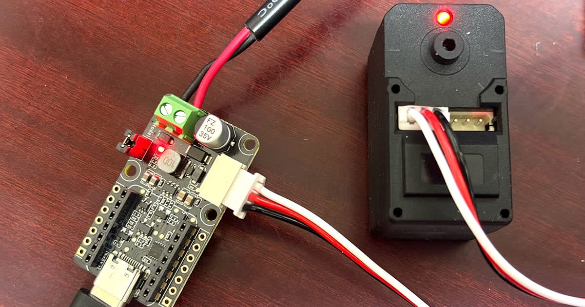
It's tedious work, but since you just follow the on-screen instructions, there's nothing confusing about it.
Assembly
Reference Resources
For detailed assembly steps, please refer to the following official resources.
- WowRobo Assembly Guide (video) — You can watch the entire assembly process
- HuggingFace SO-101 Official Documentation — Model combination videos and text-based instructions
- Seeed Studio Wiki — Rich information specific to the Pro Kit
This article focuses on what I noticed during the actual assembly rather than reproducing the steps.
Assembling the Follower Arm
Assembling the follower arm took about 2 hours. As long as you follow along with the WowRobo video, there's nothing particularly difficult. It's a repetitive process of securing 3D printed parts and servo motors with screws.
One note about cable routing. In the WowRobo video, cables are threaded after assembly is complete, but personally I found it easier to route the cables at the same time as assembling. Before attaching parts, there's plenty of room for cable management, but after everything is assembled, threading cables through the gaps between parts is quite difficult.
If you need to thread cables afterwards, having a slim pair of needle-nose pliers or a connector remover will help. I made the mistake of doing the back-wiring for the first few sections and struggled to push cables through the gaps between parts.
Assembling the Leader Arm
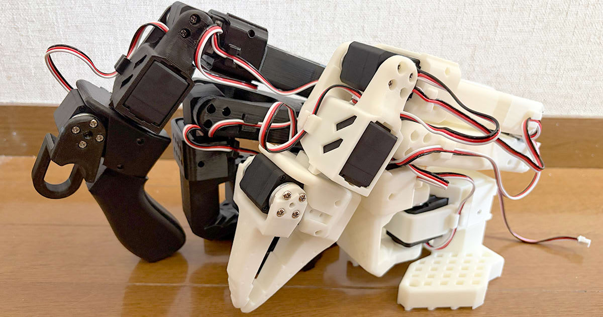
The leader arm took about 1.5 hours to complete. The basic structure is the same as the follower, but since the servo model numbers differ by joint, you need to be careful not to install the wrong servo in the wrong joint.
What made the leader arm assembly a bit tricky was the lack of reference photos. The WowRobo video mainly covers follower arm assembly and doesn't address much about leader arm-specific part placement. The HuggingFace documentation is also more follower-oriented. In the end, the Seeed Studio Wiki was the most helpful resource.
Calibration
After assembly is complete, calibrate each joint. For calibration, the video in the HuggingFace documentation is helpful.
Follower Calibration
The follower calibration completed without issues.
uv run lerobot-calibrate \
    --robot.type=so101_follower \
    --robot.port=/dev/tty.usbmodemXXXX \
    --robot.id=my_follower
Simply follow the on-screen instructions to move the arm into the specified pose and press Enter.
Leader Calibration (Multi-turn Issue)
During leader calibration, I encountered an error at the elbow_flex joint. This is where I got stuck the most this time, so I'll describe it in detail.
uv run lerobot-calibrate \
    --teleop.type=so101_leader \
    --teleop.port=/dev/tty.usbmodemYYYY \
    --teleop.id=my_leader
The following error appeared during calibration.
Magnitude 2943 exceeds 2047
Cause
The position register (Present_Position) of the STS3215 servo had accumulated multi-turn values. The value, which should normally stay within the range of 0 to 4095, had become a large value like 33644 because the axis was apparently rotated many times during assembly...
Diagnostic Steps
I used scservo_sdk to directly read the servo's position register to check.
from scservo_sdk import PortHandler, PacketHandler

port = PortHandler('/dev/tty.usbmodemXXXX')
port.openPort()
port.setBaudRate(1000000)

ph = PacketHandler(0)

# Read Present_Position (register 56)
motor_id = 4  # elbow_flex
pos, result, error = ph.read2ByteTxRx(port, motor_id, 56)
print(f"Raw position: {pos}")
# => 33644 (abnormal value, normally should be around 2048)
The position value was 33644, clearly exceeding the normal range (around 2048).
Resolution Steps
The issue was resolved by resetting the Homing_Offset register and performing a power cycle.
# Reset Homing_Offset (register 33) to 0
ph.write2ByteTxRx(port, motor_id, 33, 0)
- Write 0 to Homing_Offset (register 33) with the code above
- Unplug both the USB cable and DC power, and wait about 5 seconds
- Reconnect and verify that the raw position has returned to the normal range (around 2048)
A complete power cutoff is important. Even if you only unplug the USB cable, a small current may continue to flow to the servo, so be sure to unplug the DC power as well.
After confirming recovery, run the calibration again. This time it completed without issues.
Teleoperation
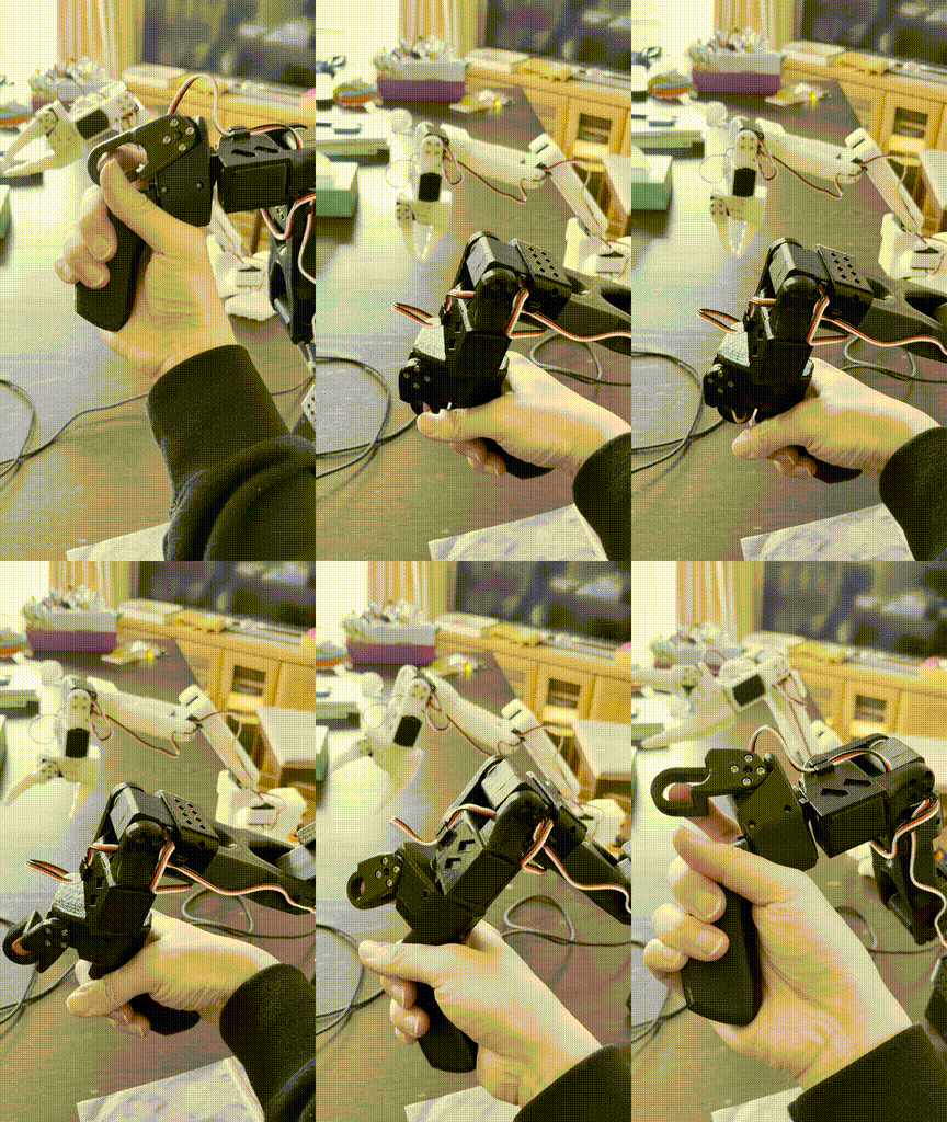
Now for the main event: teleoperation. Moving the leader arm by hand causes the follower arm to follow its movements.
Personally, it was as exciting as when the Family Computer Robot first moved :)
Checking Ports
When connecting 2 USB adapters simultaneously, the port numbers may be assigned differently than when connecting them individually. Before teleoperation, use lerobot-find-port to confirm the ports for both the follower and leader.
uv run lerobot-find-port
Running Teleoperation
uv run lerobot-teleoperate \
    --robot.type=so101_follower \
    --robot.port=/dev/tty.usbmodemXXXX \
    --robot.id=my_follower \
    --teleop.type=so101_leader \
    --teleop.port=/dev/tty.usbmodemYYYY \
    --teleop.id=my_leader
It operated stably at 60Hz. Moving the leader arm causes the follower arm to follow in near real-time. Seeing the follower move exactly as operated by hand, including gripper opening and closing, was a moment of excitement.
In the previous article, I was operating the yellow robot arm in Isaac Sim with sliders in Physics Inspector, but actually moving it by hand feels completely different. You can physically experience things that aren't visible in simulation, such as joint backlash (play) and servo torque characteristics.
Summary of Pitfalls
Here's a summary of the problems encountered during this work.
| Problem | Cause | Solution |
|---|---|---|
| TypeError with Python 3.14 | draccus is not compatible with Python 3.14 | Create environment specifying Python 3.12 |
| Magnitude exceeded during calibration | STS3215 position register accumulated multi-turn values | Homing_Offset reset + power cycle |
| Port numbers change when 2 ports are connected | Port assignment changes when USB adapters are connected simultaneously | Check each time with lerobot-find-port |
| Limited assembly information for leader arm | Official videos/documentation are follower-oriented | Refer to Seeed Studio Wiki |
Summary
I went through the entire process from assembling the SO-ARM101 Pro kit to teleoperation. Assembly took approximately 2 hours for the follower and about 1.5 hours for the leader, for a total of about 3.5 hours. Including calibration and teleoperation verification, I think you can get it working in half a day.
What personally impressed me most was the difference in feel between simulation and the real machine. In Isaac Sim, I was moving joints with Physics Inspector sliders, but when you hold the real leader arm in your hand and operate it, you get physical feedback like the different weight of each joint and the feel of the gripper opening and closing. I felt that this "hands-on" experience is meaningful for understanding the Sim2Real gap.
The multi-turn issue during calibration is a problem that others who purchase the same kit may encounter. I've recorded the diagnostic steps for directly reading registers with scservo_sdk, so I hope it serves as a reference if you encounter the same symptoms.
Next, I plan to connect a USB camera, set up a data collection environment, and try imitation learning with LeRobot's ACT policy.