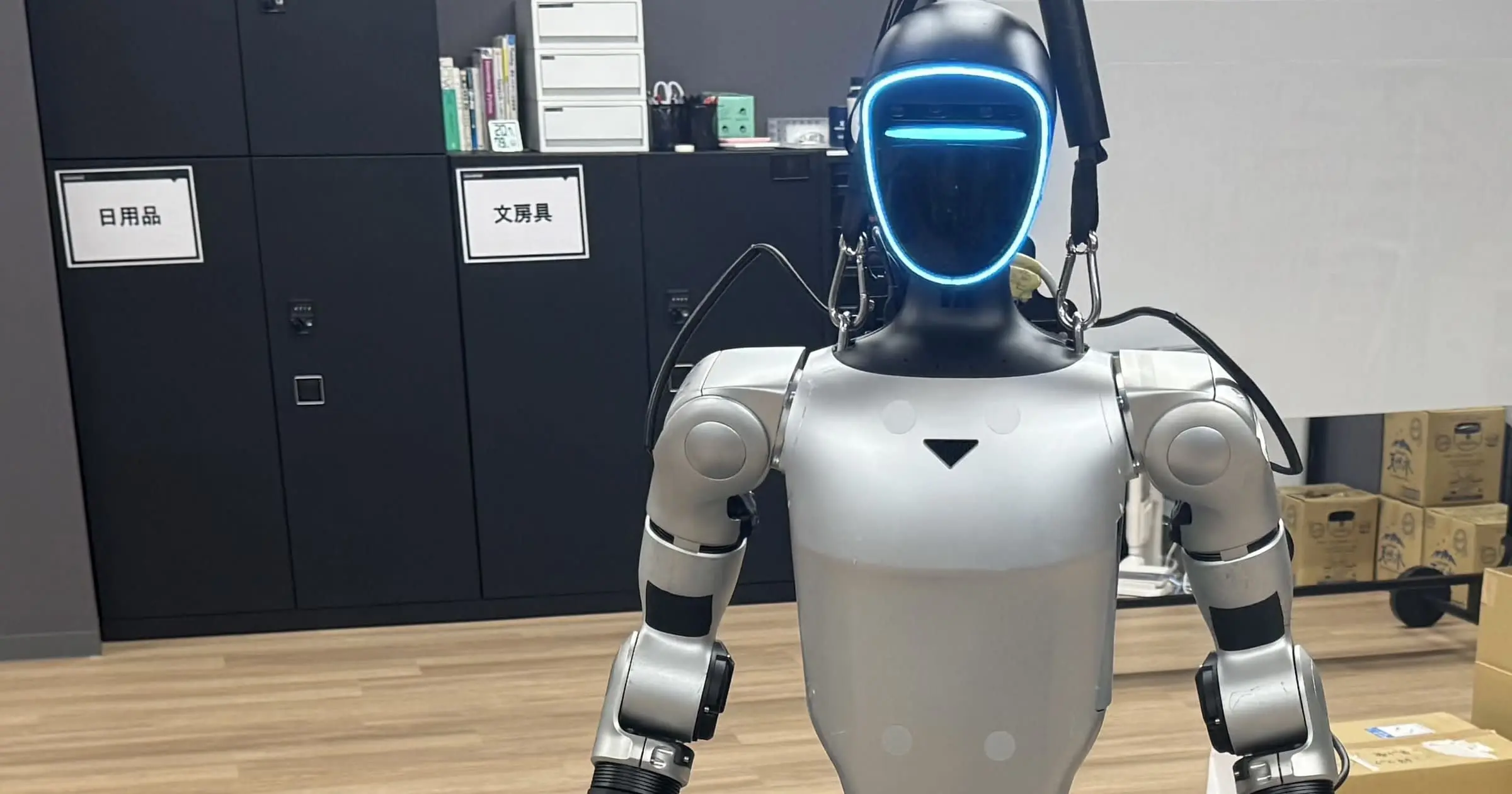
# Unitree G1 Bottle Grasping and Lifting Reinforcement Learning Project with Isaac Lab and PPO: Sim-to-Real Grasping and Lifting of a 600ml Bottle on Real Hardware, Completing the Proof of Concept

This page has been translated by machine translation. View original
Introduction
In the previous article, I introduced the bottle grasping and lifting reinforcement learning for the Unitree G1 Inspire Hand built on Isaac Lab, from simulation to the entry point of real-world deployment.
The main results confirmed up to that point were as follows.
| Item | Result |
|---|---|
| Stage 1 modular evaluation | 768 / 768 |
| Stage 2 modular evaluation | 766 / 768 |
| Object-relative corrected integration | 748 / 768, 97.40% |
| Practical asymmetric workspace | 648 / 768, 84.375% |
| DGX Spark standalone inference | Passed |
| Real G1 state acquisition | Passed |
| Real Inspire Hand state acquisition | Passed |
| Real Stage -1 arm transition | Passed |
| First bounded Stage 2 command | Passed |
| Real object grasp / lift | Not yet tested |
At the end of the previous article, I had confirmed moving the right arm to the task-ready pose on the real G1 and sending the bounded hand command generated by the Stage 2 actor.
However, I had not yet reached the point of grasping an actual bottle, let alone lifting a bottle with contents.
This week, I bridged this final sim-to-real gap.
Ultimately,
Normal standing
  ↓
safe arm transition
  ↓
palm-left pregrasp
  ↓
Stage 2 RL-assisted grasp
  ↓
holding a PET bottle with approximately 600 ml of contents
  ↓
two-stage lift
  ↓
bottle actually lifts off the table
was confirmed on the real hardware.
This article summarizes the following work carried out in the process.
- Real-world grasp using Stage 2 policy
- Real-world pre-shape adjustment for Inspire Hand
- Handling the hardware constraint of a broken right-hand ring finger
- Gradual transition from an empty bottle to an approximately 600 ml bottle
- Failure where lift barely occurred on the real hardware
- Verification of URDF joint limits
- Tracking analysis of command target vs. actual joint state
- Comparison of no-load / loaded conditions
- Measured compensation for steady-state tracking error
- Nominal 6 cm two-stage lift
- Final real-world demo
- Why Stage 1 actor was not used on the real hardware this time
- Connection to the next Visual Manipulation Project
In the final demo of this article, I confirm grasping an approximately 600 ml filled PET bottle and lifting it off the table.
On the other hand, stable place-back has not been completed. The bottle is still likely to be dropped during descent and release, so in the demo, a person receives the bottle for safety.
Also, in this final real-world PoC, the bottle position is via manual placement, not camera-based autonomous manipulation.
Using Only Stage 2 in This Real-World PoC
In simulation, I had ultimately built the following pipeline.
Stage 0:
  geometric coarse bias
      ↓
Stage 1:
  learned safe approach
      ↓
controlled ingress
      ↓
Stage 2:
  learned grasp residual
      ↓
lift
      ↓
retention
model_149 was used for Stage 1, and model_100 for Stage 2.
However, in this real-world PoC, the Stage 1 actor was not used directly.
The only learned policy used on the real hardware was Stage 2's model_100.
The reason is that the role of Stage 1 is essentially,
bottle position
  ↓
outer target
  ↓
right-arm approach
an object-relative approach.
The current real-world runtime does not yet have a perception pipeline that estimates the bottle position in real-time using images from the G1 camera.
Inputting a nominal bottle position into Stage 1 in that state would not constitute "autonomous approach using vision."
Therefore, in this PoC, I prioritized completing the manipulation part first.
manual bottle placement
  ↓
validated scripted arm approach
  ↓
Stage 2 RL-assisted grasp
  ↓
lift
In other words, the real-world results this time are positioned as,
A sim-to-real PoC of the Stage 2 manipulation policy.
Stage 1 was not left unused because it couldn't be used; it is being saved for use in the next project (vision integration).
Real-World Stage 2 Runtime
The Stage 2 actor is the same model_100 as before.
The network architecture is as follows.
input:
  53D

network:
  53
   ↓
  256
   ↓
  128
   ↓
  64
   ↓
   12

activation:
  ELU
Stage 2 is not an end-to-end policy that replaces the entire scripted grasp trajectory.
The actual configuration is,
scripted calibrated grasp base
  +
bounded Stage 2 learned residual
In other words,
q_candidate
  = q_base + residual_scale × actor_output
is a hybrid configuration.
This time as well, Stage 2 is used with deterministic inference.
The residual scale is 0.08, same as in simulation.
Also, a unilateral constraint in the closing direction was maintained.
candidate
  = max(candidate, base)
The simulator-side convention is converted to real motor-space.
Therefore, the policy will not suddenly issue a large command in the direction of opening the hand.
Inspire Hand's 12D Simulation Representation and 6D Real-World Motor Space
The right hand used in simulation is represented by 12 articulated joints.
On the other hand, the real Inspire Hand treats the right hand as a 6D motor-space.
The motor order used this time is as follows.
0: pinky
1: ring
2: middle
3: index
4: thumb bend
5: thumb rotation
In the real motor command,
0:
  close

1:
  open
is the direction.
Since the Stage 2 actor generates a 12D target, on the real hardware,
real motor-space q6
  ↓
simulator-side articulated q12
  ↓
Stage 2 actor
  ↓
12D candidate
  ↓
DFQ manifold projection
  ↓
real motor-space q6
an adapter is used.
The actor output is not sent purely and directly to the motors.
The Right-Hand Ring Finger of the Inspire Hand Used Was Broken
The real-world Inspire Hand used this time had an important hardware constraint.
The right-hand ring finger was broken and could not be independently controlled normally.
Therefore, if you watch the final demo video, you can see that only the ring finger is not opening and closing like the other fingers.
This is not behavior caused by,
Stage 2 policy failure
motor mapping failure
projection failure
It is a hardware failure specific to the real-world hand used this time.
Therefore, in the real-world grasp,
index
middle
pinky
thumb
were primarily utilized, while the ring finger remained in a state where it could not be independently controlled normally.
Since simulation uses a model where all 5 fingers operate normally, this is one clear sim-to-real difference.
This time, the policy was not retrained to compensate for this failure.
First,
Under the currently available hardware condition, how far can we get with the existing Stage 2 policy and real-world calibration?
was the approach taken to confirm.
Ultimately, even with this hardware constraint present, it was possible to grasp an approximately 600 ml PET bottle and lift it off the table.
Pre-shape Needed to Be Readjusted on the Real Inspire Hand
Initially, the pre-shape designed in simulation was projected and used as-is.
However, on the real hardware, the fingers were more curled than expected before the start of the grasp.
In particular, since only part of the pre-shape command was being updated, q0 through q3 retained the influence of the startup state.
Therefore, for the pregrasp, a full-open target was explicitly given to all 6 right-hand motors.
q0 = 1.0
q1 = 1.0
q2 = 1.0
q3 = 1.0
q4 = 1.0
q5 = 1.0
However, as mentioned above, for the ring finger, independent operation as commanded cannot be performed due to the failure on the real hardware side.
Even so, for the fingers that operate normally, using the full-open pose greatly reduced fingertip interference when approaching the PET bottle from the side.
On the real hardware, the policy of
prioritizing actually observed hand geometry and hardware conditions over the simulator-side nominal pose
was adopted.
Wrist Orientation Also Adjusted on the Real Hardware
Another important factor was wrist roll.
Initially, candidates such as
1.20
0.90
0.60
0.35
0.16 rad
were checked step by step.
Afterwards, to turn the palm further toward the bottle, ultimately,
right_wrist_roll = 0.0 rad
was used.
In this real-world task, the geometry aimed for is,
palm:
  facing bottle side

fingers:
  wrapping the side of the bottle

thumb:
  opposition
On the real hardware, not only differences in position of a few cm, but also small differences in wrist orientation had a large impact on grasp quality.
Startup Trajectory Interferes with Table
During real-world integration, failures other than the policy also occurred.
The particularly problematic one was the startup trajectory.
A trajectory captured from the Unitree native Right Hand Up motion was used to move from normal standing to the task-ready pose.
This trajectory itself worked in free space.
However, when checking FK, the hand center midway through remains below the table top height while moving considerably forward.
Therefore, in the state of
robot startup
  +
table already present
there was a possibility of the arm interfering with the table.
Cases of actually pushing the table were also confirmed.
Therefore, in the final demo,
1. Startup without table
2. Move right arm to safe outer pose
3. Pause there for 5 seconds
4. During that time, place table and bottle
5. Person moves away from workspace
6. After countdown ends, automatically proceed to ingress
was the configuration used.
Initially, an operator gate was used where CONTINUE was entered in the terminal.
However, since the operator needed to move between the PC and the robot during demo recording, this was abolished in the final version.
5
4
3
2
1
↓
automatic ingress
is a fixed 5-second window.
If safe placement cannot be completed within the time, execution is aborted.
From Empty Bottle to Filled PET Bottle
The real-world test did not proceed directly to approximately 600 ml all at once.
First, a lightweight empty PET bottle was used.
The purpose was to confirm
arm geometry
hand geometry
finger closing direction
contact position
retention
with reduced payload influence.
After that,
Stage 2 target
full-open pre-shape
wrist orientation
ingress depth
were adjusted, and finally transitioned to an approximately 600 ml filled sealed PET bottle.
What is important here is that the 0.62 kg bottle used in simulation and the real object are not completely identical.
Simulation is a simplified rigid body.
In the real object, there are
PET deformation
label friction
mass distribution due to liquid
minor slip during grasp
finger surface friction
and other factors.
Therefore,
simulation:
  0.62 kg success
and
real:
  approximately 600 ml filled PET success
are treated as separate results.
Connecting Stage 2 RL-Assisted Grasp to the Real World
In the final grasp,
full-open pre-shape
  ↓
50% deeper ingress
  ↓
Stage 2 model_100
  ↓
bounded final hand target
  ↓
grasp target latch
this sequence was used.
Even in simulation, once retention succeeded, continuing to update the actor target caused the bottle to tilt and slip over time.
Therefore, on the real hardware as well, the final hand target was held as a latched target after grasp completion.
Stage 2 grasp
  ↓
final hand target
  ↓
latch
  ↓
maintain same target during lift
In other words, rather than allowing the actor to freely update the hand target during lift, the successful grasp command is fixed.
This is an example of failure analysis obtained in simulation being directly reflected in supervisory control of the real runtime.
First Approximately 600 ml Real-World Grasp
With this configuration, for an approximately 600 ml filled PET bottle,
side approach
  ↓
finger wrap
  ↓
thumb opposition
  ↓
retention
was confirmed up to this point.
Since the right-hand ring finger is broken, it is not a 5-finger grasp identical to simulation.
Even so, a grasp was established primarily using the normally functioning fingers and thumb.
Here, the first major sim-to-real milestone was achieved.
However, the next problem arose.
The bottle could be held, but it barely lifted upward.
Failure: Commanding +2 cm Lift Results in Almost No Upward Movement
The initial lift used a local Cartesian-to-arm mapping measured around the task-ready pose.
Representative joint corrections in the +Z direction are as follows.
| Joint | +Z coefficient |
|---|---|
| right shoulder pitch | +0.1836 rad/m |
| right shoulder roll | -0.0313 rad/m |
| right shoulder yaw | +0.1120 rad/m |
| right elbow | -2.9553 rad/m |
Requesting +2 cm means for the right elbow, roughly,
-2.9553 × 0.02
≈ -0.0591 rad
as the command.
There is no problem in the kinematic model.
However, on the real hardware, the arm was not moving as much as commanded.
Initially, the suspicion was,
Is it getting close to the robot's joint limit?
Checking URDF Joint Limits
Right arm joint limits were confirmed from the official G1 DFQ URDF.
Representative values are as follows.
| Joint | Lower | Upper |
|---|---|---|
| Shoulder pitch | -3.0892 | +2.6704 |
| Shoulder roll | -2.2515 | +1.5882 |
| Shoulder yaw | -2.6180 | +2.6180 |
| Elbow | -1.0472 | +2.0944 |
| Wrist roll | -1.9722 | +1.9722 |
| Wrist pitch | -1.6144 | +1.6144 |
| Wrist yaw | -1.6144 | +1.6144 |
The lift elbow target at that time was,
-0.062889 rad
On the other hand, the URDF lower limit is,
-1.0472 rad
So the remaining margin to the lower limit is,
approximately 0.984 rad
There was also sufficient margin for shoulder joints similarly.
Therefore, it became clear that,
The cause of being unable to lift is not the joint-angle limit.
Comparing Commanded Joint Target and Actual State
Next, from the real-world log,
commanded target
vs
measured actual state
were compared.
In the approximately 600 ml loaded run, representative values before lift were as follows.
Right Elbow
pregrasp command:
  approximately -0.0038 rad

pregrasp actual:
  approximately +0.0695 rad

error:
  approximately +0.0733 rad
Furthermore, at the lift top,
lift target:
  -0.0629 rad

actual:
  +0.0451 rad

error:
  +0.1080 rad
In other words, in the last part of
IK / Jacobian target
     ↓
q_target
     ↓
arm controller
     ↓
q_actual
a large tracking error was occurring.
50% Deeper Ingress Was Not Actually Moving 50%
This result was important not only for lift but also for pregrasp geometry.
On the real hardware, "50% deeper ingress" had been set.
However, visually, even at 50%, the hand was not entering as close to the bottle center as expected.
Initially, increasing the command from
50%
  ↓
70%
  ↓
100%
was also considered.
However, looking at the tracking log, the problem was not the command fraction itself.
For the right elbow, for example,
command:
  approximately -0.0038 rad

actual:
  approximately +0.068 rad
In other words, the state was,
A 50% command is being sent, but the real hardware is not reaching that 50% target.
Here, rather than simply increasing the ingress fraction, it was decided to investigate controller tracking itself.
No-Load Tracking Diagnostic
To isolate whether the 600 ml payload was the cause, the same arm target was executed under conditions of
object:
  none

table:
  none

hand motion:
  none
Furthermore, the pregrasp target was held for 10 seconds and the actual joint state was recorded every 0.5 seconds.
The results were very clear.
Pregrasp
Right shoulder pitch:
target:
  -0.299587

actual:
  approximately -0.2407

error:
  approximately +0.0589 rad
Right elbow:
target:
  -0.003784

actual:
  approximately +0.0674

error:
  approximately +0.0712 rad
And even after holding for 10 seconds,
elbow error:

t = 0 s
  approximately 0.07128

t = 5 s
  approximately 0.07117

t = 10 s
  approximately 0.07115
Almost no change.
In other words,
It was not simply a matter of slow convergence.
It had reached a steady state with a certain tracking offset.
The Same Steady-State Error Occurs During Lift
The same was true for no-load lift.
Right elbow:
target:
  -0.062889

actual:
  approximately +0.0215

error:
  approximately +0.0844 rad
Even after holding for 5 seconds,
0.0845
→
0.0844
→
0.0844
there was only about this much change.
At this point, it became clear that
joint limit:
  not the cause

insufficient waiting time:
  not the cause

600 ml payload only:
  not the cause
A clear steady-state tracking offset exists even under no-load conditions.
Also Checking the Controller Packet
The arm command packet being used was also checked.
Representative values are as follows.
Right Shoulder Pitch
kp:
  90

kd:
  3

tau:
  0
Right Elbow
kp:
  60

kd:
  3

tau:
  0
Arm weight was,
weight:
  1.0
In other words, it was not a state where the target could not be reached because of low-weight takeover as in the previous case,
weight = 0.2
Also, in this PoC, Kp / Kd were not changed.
Rather than increasing stiffness on the real hardware, the approach taken was to first measure current controller behavior and then reflect the results on the trajectory side.
Adding Payload Further Degrades Lift Tracking
Comparing no-load and approximately 600 ml loaded conditions, the right elbow lift top error was as follows.
| Condition | Elbow top error |
|---|---|
| No load | approximately 0.0844 rad |
| Approximately 600 ml loaded | approximately 0.1080 rad |
The difference is,
approximately 0.0236 rad
In other words, the result was,
tracking offset exists even under no-load
+
tracking error further increases when holding payload
This result shows that,
Even if the kinematic target is correct, the real-world actuator / controller does not necessarily reach that target accurately.
In simulation,
q_target
≈
q_actual
may be treated as approximately equal.
However, on the real hardware,
q_target
!=
q_actual
This difference cannot be ignored in manipulation at the level of a few centimeters.
Measured Tracking Compensation
Therefore, it was decided to correct the command target using the steady-state error measured on the real hardware.
Defining error as,
e
  = q_actual - q_desired
This time, rather than compensating 100% from the start,
alpha = 0.25
was used as a conservative compensation,
q_command
  = q_desired - alpha × e
Pregrasp Compensation
The error measured in the no-load diagnostic was,
shoulder pitch:
  +0.058860 rad

elbow:
  +0.071147 rad
The 25% compensation is,
shoulder pitch bias:
  -0.014715 rad

elbow bias:
  -0.017787 rad
Real-World Results of 25% Compensation
Within the same run, the baseline without compensation was first measured.
Before
shoulder pitch error:
  approximately +0.05825 rad

elbow error:
  approximately +0.07121 rad
After applying 25% compensation,
After
shoulder pitch error:
  approximately +0.05329 rad

elbow error:
  approximately +0.06327 rad
Both joints showed the actual state moving in the direction of the desired pose.
The improvement was especially clear for lift.
No Compensation
elbow lift error:
  approximately +0.08436 rad
25% Compensation
elbow lift error:
  approximately +0.06201 rad
Approximately 26.5% reduction.
Also, the actual elbow position moved from
approximately +0.0215 rad
to
approximately -0.0009 rad
With this, it was confirmed on the real hardware that,
Command bias can reduce real tracking error.
On the other hand, the response was not a complete 1:1.
Therefore, this compensation is treated not as a theoretical inverse controller, but as
measured real-world calibration.
Additional Compensation for Loaded Condition
Under the approximately 600 ml loaded condition, the elbow error increased by an additional
approximately 0.023645 rad
compared to no-load.
Therefore, in the final runtime, the configuration adopted was,
no-load tracking compensation:
  25%

additional loaded elbow compensation:
  50% of measured incremental error
The additional loaded bias is approximately,
-0.01182 rad
Kp, Kd, and arm weight were not changed.
In other words, rather than
making the controller stronger
the approach is,
measure actual robot response
  ↓
adjust command trajectory
+3 cm Real-World Lift Was Still Small
The initial real-world lift was nominal +2 cm.
After introducing tracking compensation, it was further extended to nominal +3 cm.
However, looking at the actual demo, the amount of lift was still small,
The grasp is succeeding, but it is weak as a visually clear pick-and-lift.
What was important here was that a
3 cm command
does not mean an
actual 3 cm Cartesian lift
The local Jacobian generates a kinematic target, but real controller tracking error remains.
Therefore, the lift target itself was ultimately extended further.
Final Version is a Nominal 6 cm Two-Stage Lift
Rather than jumping to a large joint target all at once, the final demo divided the lift into 2 stages.
grasp
  ↓
Stage 1 lift:
  nominal +3 cm
  3.5 s
  ↓
0.75 s hold
  ↓
Stage 2 lift:
  additional nominal +3 cm
  3.5 s
  ↓
total nominal:
  +6 cm
The 6 cm here is a nominal value on the kinematic command.
It does not claim that exactly 6.0 cm was achieved on the real hardware.
What was confirmed in the final demo is,
The bottle clearly lifted off the table.
as a real-world result.
Lift Guardrails Also Changed Incrementally
Previously, an independent engineering guardrail of
MAX_LIFT_JOINT_DELTA_RAD:
  0.070 rad
was used. This is not the hardware joint limit of the G1.
For the 6 cm lift, rather than simply disabling this value,
per-stage guardrail:
  0.110 rad

total guardrail:
  0.210 rad
were separated.
The command delta for right elbow was,
Stage 1:
  approximately -0.1038 rad

Stage 2:
  approximately -0.0887 rad

Total:
  approximately -0.1924 rad
The final elbow command is,
approximately -0.2140 rad
The URDF lower limit is,
-1.0472 rad
so the remaining margin to the joint-angle limit is,
approximately 0.833 rad
In other words, even in the final demo, the hardware joint-angle limit was not approached.
Reason for Two-Stage Approach
Two-stage lift had advantages beyond simply increasing height.
By using
grasp
  ↓
small lift
  ↓
short hold
  ↓
second lift
the benefits are:
- It is easier to confirm that the grasp has not collapsed significantly after the first lift
- The command displacement per step can be kept smaller
- The lift movement is also visually clearer in the demo
- A staged trajectory can also be configured for the lowering phase
In the final runtime, the lower side was also implemented as a two-stage trajectory:
top
  ↓
intermediate lift pose
  ↓
pregrasp height
However, under the current hardware / grasp conditions, the bottle may slip during descent.
Therefore, in the final demo, stable autonomous place-back is not treated as a successful result.
Final Demo
The final real-world sequence is as follows.
Normal standing
  ↓
native safe raise
  ↓
move outward
  ↓
full-open Inspire Hand
  ↓
wrist roll = 0
  ↓
5-second table / bottle placement window
  ↓
fixed-wrist ingress
  ↓
50% deeper pregrasp
  ↓
measured tracking compensation
  ↓
Stage 2 model_100 RL-assisted grasp
  ↓
grasp target latch
  ↓
two-stage nominal +6 cm lift
  ↓
bottle leaves table
For an approximately 600 ml filled PET bottle,
Stage 2 model-derived grasp
bottle retention
visible upward motion
bottle bottom lift-off
were confirmed.
Demo Video
In the video, the right-hand ring finger does not operate like the other fingers.
This is because the right-hand ring finger of the Inspire Hand used this time is broken and cannot be independently controlled normally. It is not the case that the Stage 2 policy is intentionally stopping the ring finger.
Even with this hardware constraint present, it was possible to grasp an approximately 600 ml PET bottle and lift it off the table using the normally functioning fingers and thumb.
In this demo, successfully lifting the bottle and achieving lift-off is the success result.
On the other hand, the grasp still becomes unstable during descent and release, and there is a possibility of dropping the bottle.
Therefore, in the video, a person ultimately receives the bottle.
In this article, the distinction is made as follows:
pick:
  demonstrated

lift-off:
  demonstrated

stable autonomous place-back:
  not established
Final Real-World Pipeline
Summarizing the final version of this PoC, the configuration is as follows.
Real Stage -1:
  native G1 trajectory
      ↓
safe outer pose

Manual perception substitute:
  fixed bottle placement
      ↓
5-second insertion window

Geometric arm controller:
  fixed-wrist ingress
      ↓
50% deeper pregrasp
      ↓
measured tracking compensation

Stage 2:
  frozen model_100
      ↓
scripted base grasp
  + learned residual
      ↓
bounded real Inspire Hand target
      ↓
target latch

Lift:
  measured local Cartesian-to-arm mapping
      ↓
real tracking compensation
      ↓
payload compensation
      ↓
two-stage nominal +6 cm lift
This is not pure end-to-end RL.
This time as well, it is a hybrid system combining
learned policy
+
geometric control
+
measured real-world calibration
+
supervisory control
Why Stage 1 Was Not Included in the Final Demo
In simulation, Stage 1 was very important.
The role of Stage 1 is,
current arm state
+
bottle-relative observation
  ↓
safe outer approach
However, to use Stage 1 correctly on the real hardware,
camera image
  ↓
bottle detection
  ↓
3D position estimation
  ↓
camera frame
  ↓
robot / task frame transform
  ↓
Stage 1 observation
is required.
In this real-world PoC, this perception layer has not yet been implemented.
Bottle position is manual nominal placement.
Therefore, rather than inputting a fake nominal observation into Stage 1 to run it,
completing the sim-to-real transfer of Stage 2 manipulation first
was chosen.
As a result, the final demo is,
Stage 1:
  not used on real robot

Stage 2:
  model_100 used on real robot
This was also a conveniently structured result for future design.
Main Failures Encountered This Week
1. A Target That Rises 3 cm in Simulation Does Not Necessarily Rise 3 cm on the Real Hardware
Even if the kinematic target is correct,
q_target != q_actual
then the actual Cartesian pose will also differ.
In real manipulation,
IK accuracy
is not enough; it is also necessary to measure
controller tracking accuracy
2. A 50% Ingress Command Was Not a 50% Actual Motion
Looking only at the command fraction and judging,
50% is not enough
→ make it 100%
leads to misidentifying the cause.
The actual problem in this case was the tracking offset, not the target itself.
3. Tracking Error Did Not Disappear Even After Long Hold
In the 10-second no-load hold,
elbow error:
  approximately 0.0713
  →
  approximately 0.0711 rad
In other words, simply increasing settling time did not solve it.
4. Don't Confuse Hardware Joint Limits and Software Guardrails
The value used initially,
MAX_LIFT_JOINT_DELTA_RAD = 0.070
is an engineering guardrail that I set myself.
It is completely separate from the G1 elbow URDF limit,
lower:
  -1.0472 rad
During debugging, it is necessary to consider the following separately:
hardware limit
controller behavior
software safety bound
trajectory design bound
5. Tracking Behavior Changes with Payload
No-load elbow top error:
approximately 0.0844 rad
Loaded:
approximately 0.1080 rad
On a real robot, object mass also affects controller response.
6. Measured Compensation Is Effective but Not 1:1
The 25% command bias moved the actual pose in the desired direction.
However, during pregrasp, the actual response to the command bias was not a perfect 1:1.
Therefore, rather than simplifying as:
measured error
  ↓
100% inverse compensation
it was applied incrementally as a small bounded correction.
7. Hardware Failure Is Also Part of Sim-to-Real Gap
In simulation, all hand joints operate normally.
However, on the real Inspire Hand used this time, the right-hand ring finger was broken and could not be controlled independently in a normal manner.
Even so, rather than immediately retraining the existing policy,
current hardware
  ↓
actual grasp geometry
  ↓
bounded calibration
verification was performed in this order.
On a real robot, hardware degradation that does not exist in simulation must also be included in the system design.
8. Startup Path Is Also Part of the Manipulation System
Even if the grasp policy alone is safe, the system cannot function if the startup trajectory to reach it interferes with the table.
This time, it was found that the native raise trajectory was not table-safe, so a runtime-level workaround was added:
table absent during startup
  ↓
safe outer pose
  ↓
table insertion
9. PASS Marker and Actual Manipulation Success Are Different
Even if the runtime outputs:
PASS
it does not guarantee that the bottle was actually lifted.
In the end, judgment was made by combining:
robot log
+
joint state
+
visual observation
+
demo video
Especially in real-world robotics, it is necessary to record separately:
software sequence completed
and
physical task completed
The Most Important Thing in This Sim-to-Real
The biggest takeaway from this PoC was:
Being able to generate the correct target in simulation and having the real robot reach that target are separate problems.
The failure chain this time was:
simulation:
  lift works
      ↓
offline IK:
  lift target is valid
      ↓
URDF:
  joint limits pass
      ↓
real robot:
  lift is too small
      ↓
tracking diagnostic
      ↓
steady-state command / actual error discovered
      ↓
measured compensation
      ↓
larger two-stage lift
      ↓
real bottle lift-off
If at some point the conclusion had been:
RL policy is weak
and PPO had been retrained, the root cause of the problem might have been missed.
This time, the real-world results were improved not through additional training, but through:
measurement
+
failure isolation
+
controller-level compensation
This is similar to what happened during the previous simulation integration, when:
55.73% → 97.40%
was achieved.
At that time too, the problem was not policy capacity but coordinate semantics.
This time as well, the main issue was not the policy itself, but real-world control semantics.
Current Milestone
Simulation
| Result | Value |
|---|---|
| Stage 1 modular | 768 / 768 |
| Stage 2 modular | 766 / 768 |
| Initial integrated RandPos | 428 / 768、55.73% |
| Object-relative corrected | 748 / 768、97.40% |
| Full ±5 cm square | 569 / 768、74.09% |
| Practical 10 cm × 8 cm workspace | 648 / 768、84.375% |
Deployment / Real Robot
| Item | Status |
|---|---|
| DGX Spark standalone Stage 1 actor | Passed |
| DGX Spark standalone Stage 2 actor | Passed |
| x86 / ARM64 numerical parity | Passed |
| G1 real state acquisition | Passed |
| Inspire Hand real state acquisition | Passed |
| Real Stage -1 | Passed |
| Full-open real pre-shape | Passed |
| Palm-left wrist calibration | Passed |
| Empty PET bottle grasp | Passed |
| Stage 2 model_100 real command | Passed |
| Approximately 600 ml filled PET grasp | Demonstrated |
| Loaded retention | Demonstrated |
| Real tracking diagnostic | Completed |
| Measured tracking compensation | Validated |
| Two-stage nominal +6 cm lift | Executed |
| Bottle lift-off | Demonstrated |
| Stable autonomous place-back | Not established |
| Camera-based autonomous approach | Not yet integrated |
| Real Stage 1 policy control | Not used in this PoC |
Manipulation PoC Is Now Complete for Now
This project started with a grasp / lift task using:
PET bottle
+
G1
+
Inspire Hand
+
PPO
on Isaac Lab.
After that, it progressed through:
Mass Curriculum
Stage 1
Stage 2
controlled ingress
object-relative correction
Stage 0
randomized workspace evaluation
DGX Spark deployment
real G1 arm control
real Inspire Hand adapter
real grasp
tracking compensation
loaded lift
In the end, a demo was recorded of the real G1 grasping an approximately 600 ml filled PET bottle and lifting it off the table.
Of course, this does not mean the robot manipulation system is complete.
Currently, the following constraints remain:
- manual bottle placement
- no perception
- fixed standing
- predefined workspace
- autonomous place-back incomplete
- no contact force estimation
- Inspire Hand uses position control
- the right-hand ring finger of the real Inspire Hand used is broken and cannot be independently controlled
- Stage 1 is not connected to the real robot
However, the goal of this effort was:
To take the RL policy trained in simulation to the real G1 and achieve real-object grasp / lift.
This goal is considered complete for now.
Next: Integrating Two Projects
During this internship, before this Manipulation Project, I also developed:
"A Robot Visual Inspection Agent Using Unitree Go2 and G1"
The first project dealt with the technology for:
robot camera
  ↓
visual perception
  ↓
object / risk analysis
  ↓
agent
the robot seeing the real world.
The current project, on the other hand, dealt with the technology for:
robot state
  ↓
approach
  ↓
RL grasp
  ↓
physical manipulation
the robot acting upon the real world.
The final project of the internship will connect these two.
The target pipeline is as follows:
G1 camera
  ↓
visual model
  ↓
bottle detection
  ↓
bottle position estimation
  ↓
camera-to-robot coordinate transform
  ↓
Stage 1 observation
  ↓
Stage 1 model_149
  ↓
automatic approach
  ↓
controlled ingress
  ↓
Stage 2 model_100
  ↓
automatic grasp
  ↓
lift
This is also why Stage 1 was not forced into use during the real-world PoC.
Stage 1 is fundamentally meaningful only when it receives real-world information about:
"where the bottle is."
In the next project, the camera / vision knowledge gained from the earlier Visual Inspection Agent will be used to build this missing perception layer.
By connecting:
Perception
+
Stage 1 approach
+
Stage 2 manipulation
the plan is to advance to the point where:
G1 finds the bottle using its own camera, estimates its position, and automatically approaches and grasps it.
Summary
This time, the Stage 2 policy for the Unitree G1 Inspire Hand trained on Isaac Lab was connected to the real G1.
On the real robot, full-open pre-shape, palm-left wrist orientation, and safe outer approach were confirmed step by step.
In addition, there was a hardware constraint: the right-hand ring finger of the Inspire Hand used this time was broken and could not be controlled independently in a normal manner.
Even so, RL-assisted grasp using Stage 2 model_100 was applied to a real PET bottle, and ultimately an approximately 600 ml filled PET bottle was successfully grasped.
On the other hand, the initial lift was very small, and even when nominal +2 cm / +3 cm kinematic commands were given, the arm did not rise to the expected height.
After checking the URDF joint limits, it was confirmed that joint-angle limits were not the cause.
A no-load tracking diagnostic was then performed, and it was confirmed that even after holding the target for 10 seconds, a steady-state tracking error of approximately 0.071 rad remained at the right elbow.
At lift top:
no-load:
  approximately 0.0844 rad error

approximately 600 ml loaded:
  approximately 0.1080 rad error
The tracking error increased further with payload.
Therefore, 25% of the measured steady-state error was used as a command bias.
As a result, the right elbow error during lift improved from:
approximately 0.0844
→
approximately 0.0620 rad
In the final demo, the additional tracking error under loaded conditions was partially compensated, and the nominal +3 cm was extended to a two-stage nominal +6 cm lift executed in two stages.
As a result, a demo was recorded of the real G1 grasping an approximately 600 ml filled PET bottle and actually lifting it off the table.
The Stage 1 actor was not used in the final real-robot pipeline this time.
This is because the real bottle position required for Stage 1 has not yet been obtained from the camera.
In the next project, the vision technology from the previously developed "Robot Visual Inspection Agent Using Unitree Go2 and G1" will be integrated with the manipulation technology from this project.
Ultimately, the goal is to build a Visual Manipulation Pipeline in the form of:
G1 camera
  ↓
visual model
  ↓
automatic bottle localization
  ↓
Stage 1
  ↓
Stage 2
  ↓
automatic grasp
The most important thing in this PoC was not simply sending the PPO policy to the real robot.
It was measuring each of the following one by one:
policy
geometry
coordinate semantics
action mapping
controller tracking
payload
hardware condition
safety supervisor
and isolating the gaps between simulation and the real robot.
Even after achieving a high success rate in simulation, many sim-to-real issues remained.
However, by breaking them down one by one, it was ultimately possible to reach the point of lifting a real, filled PET bottle.
This concludes the Manipulation PoC of:
"A Reinforcement Learning Project for Bottle Grasping and Lifting with Unitree G1, Starting from Isaac Lab and PPO"
for now.