Cisco C841M で 家庭内LAN と AWS を Site-to-Site VPN接続する(BGP)

こんにちは。リテールアプリ共創部のきんじょーです。
案件で Direct Connect 接続を構築する必要があり、オンプレミス側の解像度を深めるために、L2 スイッチと業務用ルーターで家庭内ネットワークを AWS に接続していきます。
前回までで、 TL-SG108E で作成したVLANに RTX1200 で VLAN 間ルーティングを構成し、店舗 LAN の縮小モデルを作りました。
今回はこの LAN を、BGP の Site-to-Site VPN で AWS に接続し、経路が自動で降ってくるところまで進めます。
当初は前回に引き続き RTX1200 を Customer Gateway にする予定でした。しかし手元の RTX1200(最終ファームウェア Rev.10.01.78)では、IPsec のトラフィックセレクタ(トンネルで転送するパケットの範囲)に 0.0.0.0/0 を指定できませんでした(ipsec ike local id への設定が Error: Unrecognized netmask parameter で拒否されます)。BGP の通信が流れるトンネル内のアドレス帯(169.254.x.x)と、実データのアドレス帯(10.100.x.x ⇔ 10.10.x.x)を 1 つのセレクタで同時にカバーする方法を見つけられず、この環境では BGP による経路伝播まで持ち込めませんでした。静的ルーティングであれば Site-to-Site VPN を張ることはできましたが、今回は DX の予行演習として BGP がやりたいので、中古の Cisco C841M を用意して再挑戦します。
今回の構成
- CGW: Cisco C841M-4X-JSEC/K9。ONU 一体型ルーターの NAT 配下に設置します
- AWS 側: VPC(10.10.0.0/16)+ VGW(ASN 64512)+ 動的ルーティングの Site-to-Site VPN
物理構成
論理構成
やってみる
VLAN 間ルーティング(Cisco 編)
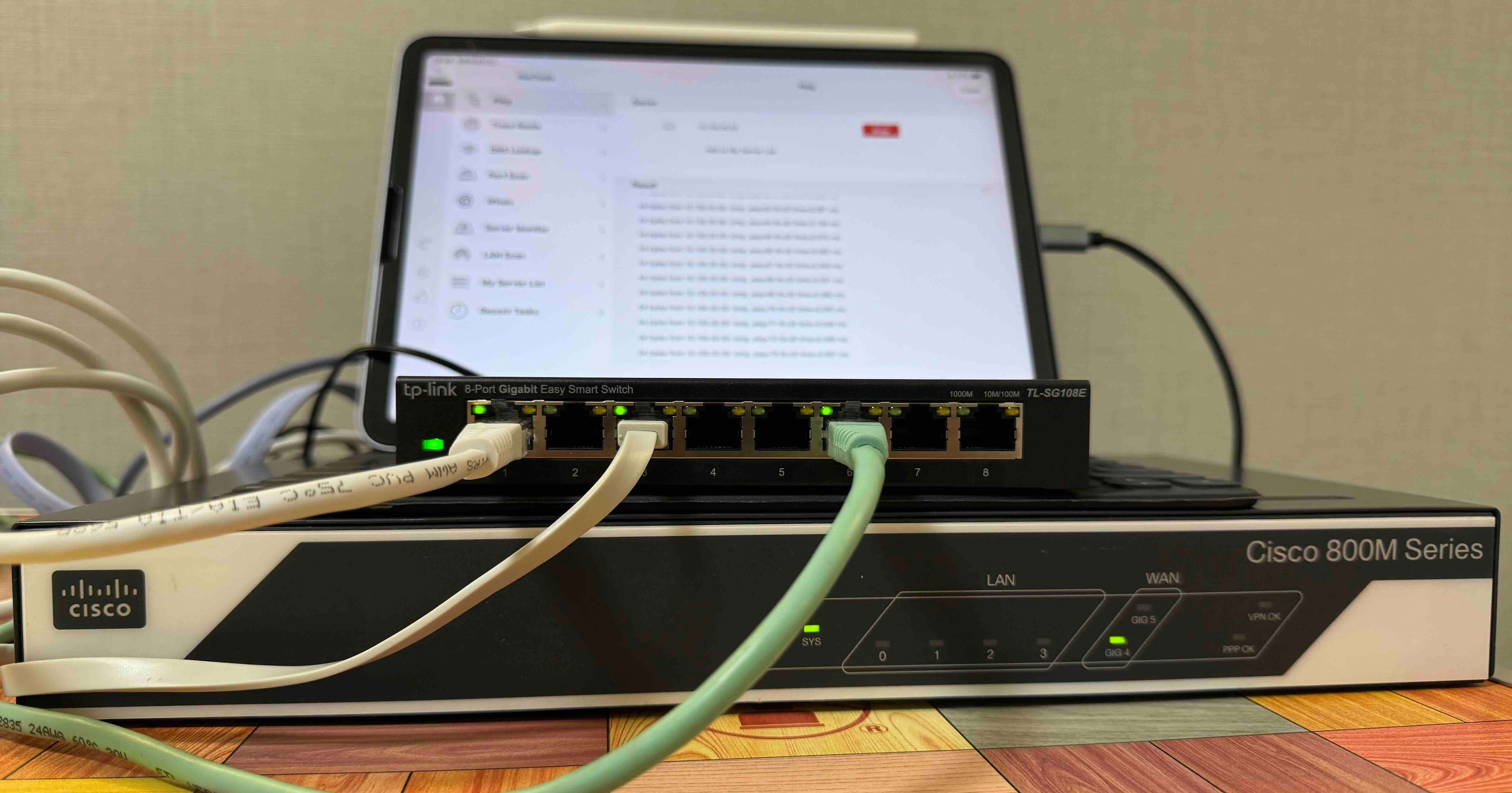
まずは結線です。
- CONSOLE ポート → Mac(USB-シリアル変換)
- Gi0/0 → TL-SG108E の port1(トランク)
- Gi0/4 → ONU 一体型ルーターの LAN ポート
TL-SG108E 側の VLAN 設定(U/T/PVID)は前回のものをそのまま使います。
結線しただけの状態で、インターフェースを確認します。
Router>show ip interface brief
Interface                  IP-Address      OK? Method Status                Protocol
GigabitEthernet0/0         unassigned      YES unset  up                    up
GigabitEthernet0/1         unassigned      YES unset  down                  down
GigabitEthernet0/2         unassigned      YES unset  down                  down
GigabitEthernet0/3         unassigned      YES unset  down                  down
GigabitEthernet0/4         192.168.1.25    YES DHCP   up                    up
GigabitEthernet0/5         unassigned      YES unset  administratively down down
Vlan1                      unassigned      YES unset  up                    up
- Gi0/0(スイッチ)と Gi0/4(ONU 一体型ルーター)がリンクアップしています。C841M の Gi0/0〜0/3 は L2 スイッチとして動くポートで、この筐体はルーターとスイッチの同居構成です
- Gi0/4 には DHCP でアドレスが付いています。
設定に入る前に、IOS(Internetwork Operating System。Cisco のネットワーク機器に搭載されている OS)の CLI モードを確認します。IOS のプロンプトは権限ごとに分かれていて、Router>(閲覧)→ enable で Router#(運用操作)→ configure terminal で Router(config)#(設定変更)と進みます。
設定を打ち終えたら end で Router# に戻り、write memory で保存する、が基本の流れのようです。
VLAN の設定を行います。
Router(config)#vlan 10
Router(config-vlan)# name TERMINAL
Router(config-vlan)#vlan 20
Router(config-vlan)# name INTERNAL
Router(config-vlan)#exit
続いて、各 VLAN のゲートウェイになる SVI(VLAN インターフェース)に IP アドレスを付けます。C841M の LAN 4 ポート(Gi0/0〜0/3)は L2 スイッチとして動くため、IP はポートにではなく SVI に付けます。
Router(config)# interface Vlan1
Router(config-if)#  ip address 192.168.100.1 255.255.255.0
Router(config-if)# interface Vlan10
Router(config-if)#  ip address 10.100.10.1 255.255.255.0
Router(config-if)# interface Vlan20
Router(config-if)#  ip address 10.100.20.1 255.255.255.0
スイッチへ向かう Gi0/0 をトランクにします。ここで 1 つ怒られました。
Router(config)# interface GigabitEthernet0/0
Router(config-if)#  switchport mode trunk
Router(config-if)#  switchport trunk native vlan 1
Router(config-if)#  switchport trunk allowed vlan 1,10,20
Command rejected: Bad VLAN allowed list. You have to include all default vlans, e.g. 1-2,1002-1005.
1002〜1005 は FDDI や Token Ring という過去の LAN 規格向けに予約された、削除できないデフォルト VLAN です(show vlan-switch brief に act/unsup として常に表示されます)。この機種ではトランクの許可リストにこれらを含める必要がありました。
Router(config-if)# switchport trunk allowed vlan 1,10,20,1002-1005
最後に DHCP です。ヤマハの dhcp scope は「.50〜.99 を配る」と配る範囲そのものを指定する方式でしたが、IOS の ip dhcp pool はサブネット全体が配布対象になるため、ip dhcp excluded-address で固定利用分を引き算して配布範囲を作ります。書き方は逆でも、表現したいことは同じです。ここでは .1〜.49 をルーター自身と固定 IP の機器用に確保し、.50 以降を配ります。
Router(config)# ip dhcp excluded-address 192.168.100.1 192.168.100.49
Router(config)# ip dhcp excluded-address 10.100.10.1 10.100.10.49
Router(config)# ip dhcp excluded-address 10.100.20.1 10.100.20.49
Router(config)# ip dhcp pool MAINT
Router(dhcp-config)#  network 192.168.100.0 255.255.255.0
Router(dhcp-config)#  default-router 192.168.100.1
Router(dhcp-config)# ip dhcp pool VLAN10
Router(dhcp-config)#  network 10.100.10.0 255.255.255.0
Router(dhcp-config)#  default-router 10.100.10.1
Router(dhcp-config)# ip dhcp pool VLAN20
Router(dhcp-config)#  network 10.100.20.0 255.255.255.0
Router(dhcp-config)#  default-router 10.100.20.1
Router(dhcp-config)# end
Router# write memory
動作確認
VLAN とトランクの状態を確認します。
Router#show vlan-switch brief

VLAN Name                             Status    Ports
---- -------------------------------- --------- -------------------------------
1    default                          active    Gi0/1, Gi0/2, Gi0/3
10   TERMINAL                         active
20   INTERNAL                         active
1002 fddi-default                     act/unsup
1003 token-ring-default               act/unsup
1004 fddinet-default                  act/unsup
1005 trnet-default                    act/unsup
Router#show interfaces gi0/0 switchport
Name: Gi0/0
Switchport: Enabled
Administrative Mode: trunk
Operational Mode: trunk
Administrative Trunking Encapsulation: dot1q
Operational Trunking Encapsulation: dot1q
(中略)
Trunking VLANs Enabled: 1,10,20,1002-1005
Trunking VLANs Active: 1,10,20
トランク化した Gi0/0 が VLAN 1 のポート一覧から消え、タグ 10・20 を運ぶポートになりました。経路表も見てみます。
Router#show ip route
(凡例部分は省略)
Gateway of last resort is 192.168.1.1 to network 0.0.0.0

S*    0.0.0.0/0 [254/0] via 192.168.1.1
      10.0.0.0/8 is variably subnetted, 4 subnets, 2 masks
C        10.100.10.0/24 is directly connected, Vlan10
L        10.100.10.1/32 is directly connected, Vlan10
C        10.100.20.0/24 is directly connected, Vlan20
L        10.100.20.1/32 is directly connected, Vlan20
      192.168.1.0/24 is variably subnetted, 3 subnets, 2 masks
C        192.168.1.0/24 is directly connected, GigabitEthernet0/4
S        192.168.1.1/32 [254/0] via 192.168.1.1, GigabitEthernet0/4
L        192.168.1.25/32 is directly connected, GigabitEthernet0/4
      192.168.100.0/24 is variably subnetted, 2 subnets, 2 masks
C        192.168.100.0/24 is directly connected, Vlan1
L        192.168.100.1/32 is directly connected, Vlan1
C(connected)は SVI に IP を付けたことで自動的に載った直結ネットワークへの経路、L(local)はルーター自身のアドレスを表す /32 の経路ですS* 0.0.0.0/0は誰も設定していないのに居ます。Gi0/4 の DHCP がデフォルトゲートウェイの情報ごと持ってきたものです
最後に iPad を VLAN10 のポートに挿すと DHCP で 10.100.10.50 台のアドレスが付き、VLAN20 と VLAN10 の間で ping が通りました。VLAN 間ルーティングは完成です。
% ping -c 3 10.100.10.50
PING 10.100.10.50 (10.100.10.50): 56 data bytes
64 bytes from 10.100.10.50: icmp_seq=0 ttl=63 time=2.530 ms
64 bytes from 10.100.10.50: icmp_seq=1 ttl=63 time=2.428 ms
64 bytes from 10.100.10.50: icmp_seq=2 ttl=63 time=2.214 ms

--- 10.100.10.50 ping statistics ---
3 packets transmitted, 3 packets received, 0.0% packet loss
round-trip min/avg/max/stddev = 2.214/2.391/2.530/0.132 ms
AWS 側の構築作業
AWS 側は VPC、サブネット、ルートテーブル、VGW、CGW、Site-to-Site VPN、疎通確認用のEC2 をCloudFormation で構築します。
EC2 は UserData で HTTP サーバーを起動しておきます。
AWSTemplateFormatVersion: "2010-09-09"
Description: >
  C841M BGP VPN lab: VPC + VGW + CGW + dynamic Site-to-Site VPN + test EC2.

Parameters:
  HomeGlobalIp:
    Type: String
    Description: On-premises (home) global IP for the Customer Gateway
  LatestAmiId:
    Type: AWS::SSM::Parameter::Value<AWS::EC2::Image::Id>
    Default: /aws/service/ami-amazon-linux-latest/al2023-ami-kernel-default-arm64

Resources:
  Vpc:
    Type: AWS::EC2::VPC
    Properties:
      CidrBlock: 10.10.0.0/16
      EnableDnsSupport: true
      EnableDnsHostnames: true
      Tags:
        - { Key: Name, Value: c841m-bgp-lab }

  Subnet:
    Type: AWS::EC2::Subnet
    Properties:
      VpcId: !Ref Vpc
      CidrBlock: 10.10.1.0/24
      AvailabilityZone: !Select [0, !GetAZs ""]
      Tags:
        - { Key: Name, Value: c841m-bgp-lab }

  RouteTable:
    Type: AWS::EC2::RouteTable
    Properties:
      VpcId: !Ref Vpc
      Tags:
        - { Key: Name, Value: c841m-bgp-lab }

  SubnetRouteTableAssociation:
    Type: AWS::EC2::SubnetRouteTableAssociation
    Properties:
      SubnetId: !Ref Subnet
      RouteTableId: !Ref RouteTable

  Vgw:
    Type: AWS::EC2::VPNGateway
    Properties:
      Type: ipsec.1
      AmazonSideAsn: 64512
      Tags:
        - { Key: Name, Value: c841m-bgp-lab }

  VgwAttachment:
    Type: AWS::EC2::VPCGatewayAttachment
    Properties:
      VpcId: !Ref Vpc
      VpnGatewayId: !Ref Vgw

  # BGP で受け取った経路をルートテーブルへ自動反映する
  VgwRoutePropagation:
    Type: AWS::EC2::VPNGatewayRoutePropagation
    DependsOn: VgwAttachment
    Properties:
      RouteTableIds:
        - !Ref RouteTable
      VpnGatewayId: !Ref Vgw

  Cgw:
    Type: AWS::EC2::CustomerGateway
    Properties:
      Type: ipsec.1
      BgpAsn: 65001
      IpAddress: !Ref HomeGlobalIp
      Tags:
        - { Key: Name, Value: c841m-bgp-lab }

  Vpn:
    Type: AWS::EC2::VPNConnection
    Properties:
      Type: ipsec.1
      StaticRoutesOnly: false
      CustomerGatewayId: !Ref Cgw
      VpnGatewayId: !Ref Vgw
      Tags:
        - { Key: Name, Value: c841m-bgp-lab }

  Ec2SecurityGroup:
    Type: AWS::EC2::SecurityGroup
    Properties:
      GroupDescription: Allow ICMP/HTTP from on-premises segments
      VpcId: !Ref Vpc
      SecurityGroupIngress:
        - { IpProtocol: icmp, FromPort: -1, ToPort: -1, CidrIp: 10.100.0.0/16 }
        - { IpProtocol: icmp, FromPort: -1, ToPort: -1, CidrIp: 192.168.100.0/24 }
        - { IpProtocol: tcp, FromPort: 80, ToPort: 80, CidrIp: 10.100.0.0/16 }
        - { IpProtocol: tcp, FromPort: 80, ToPort: 80, CidrIp: 192.168.100.0/24 }
      Tags:
        - { Key: Name, Value: c841m-bgp-lab }

  TestInstance:
    Type: AWS::EC2::Instance
    Properties:
      InstanceType: t4g.nano
      ImageId: !Ref LatestAmiId
      SubnetId: !Ref Subnet
      PrivateIpAddress: 10.10.1.65
      SecurityGroupIds:
        - !Ref Ec2SecurityGroup
      UserData:
        Fn::Base64: |
          #!/bin/bash
          mkdir -p /var/www
          echo "hello from VPC (10.10.1.65)" > /var/www/index.html
          nohup python3 -m http.server 80 --directory /var/www &
      Tags:
        - { Key: Name, Value: c841m-bgp-lab }

Outputs:
  VpnConnectionId:
    Value: !Ref Vpn
  VgwId:
    Value: !Ref Vgw
  CgwId:
    Value: !Ref Cgw
  TestInstancePrivateIp:
    Value: 10.10.1.65
生成された config と NAT 配下の修正
デプロイが完了したら Site-to-Site VPN の設定をダウンロードします。
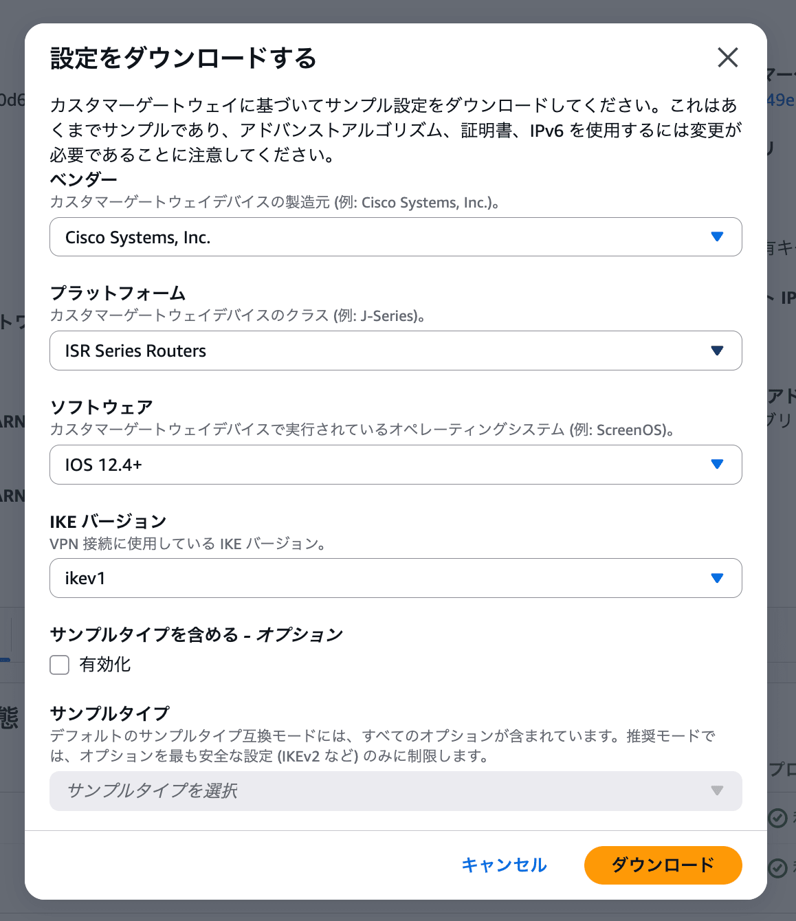
そのまま投入はできず、修正が 4 種類必要でした。
1. 自分のアドレスをインターフェース参照に変える(3 箇所)
生成 config は「あなたの外側アドレス = グローバル IP」という前提で書かれていますが、今回の検証環境下では、実際に IKE を喋る自分のアドレスは NAT 配下の Gi0/4(192.168.1.25)です。crypto keyring と crypto isakmp profile の local-address、interface Tunnel1 の tunnel source の 3 箇所を GigabitEthernet0/4 に書き換えます。
IP 直書きでも設定できますがインターフェース名で書いておくと DHCP でアドレスが変わっても追従します。なお NAT 越えのための NAT-T は、IOS では自動検出されるため追加の設定はありませんでした。
2. default-originate と network 0.0.0.0 を消す
サンプルは「CGW からデフォルトルートを広報する」例になっています。このまま入れると VPC のルートテーブルに 0.0.0.0/0 → VPN が伝播し、VPC の外向き通信が自宅に吸い込まれるため削除します。
3. 自宅 LAN の広報を足す
生成 config には自宅側のネットワークを広報する設定が入っていないため、network 文を自分で足します。
4. crypto isakmp keepalive の書式
サンプルにある keepalive の行は、投入時に拒否されました。
Router(config)#crypto isakmp keepalive threshold 10 retry 10
                                       ^
% Invalid input detected at '^' marker.
threshold ... retry ... は同じ Cisco でも ASA(ファイアウォール製品)系の文法で、IOS では数字を直接並べます(crypto isakmp keepalive 10 10)。ベンダー公式の生成 config にも、別製品の方言が混ざっていることがあるようです。
修正後の投入 config です(事前共有鍵はマスクしています)。
crypto isakmp policy 200
 encryption aes 128
 authentication pre-share
 group 2
 lifetime 28800
 hash sha
!
crypto keyring keyring-vpn-xxxxxxxx-0
 local-address GigabitEthernet0/4
 pre-shared-key address 52.68.237.171 key ********
!
crypto isakmp profile isakmp-vpn-xxxxxxxx-0
 local-address GigabitEthernet0/4
 match identity address 52.68.237.171
 keyring keyring-vpn-xxxxxxxx-0
!
crypto ipsec transform-set ipsec-prop-vpn-xxxxxxxx-0 esp-aes 128 esp-sha-hmac
 mode tunnel
!
crypto ipsec profile ipsec-vpn-xxxxxxxx-0
 set pfs group2
 set security-association lifetime seconds 3600
 set transform-set ipsec-prop-vpn-xxxxxxxx-0
!
crypto ipsec df-bit clear
crypto isakmp keepalive 10 10
crypto ipsec security-association replay window-size 128
crypto ipsec fragmentation before-encryption
!
interface Tunnel1
 ip address 169.254.14.78 255.255.255.252
 ip virtual-reassembly
 tunnel source GigabitEthernet0/4
 tunnel destination 52.68.237.171
 tunnel mode ipsec ipv4
 tunnel protection ipsec profile ipsec-vpn-xxxxxxxx-0
 ip tcp adjust-mss 1379
 no shutdown
!
router bgp 65001
 neighbor 169.254.14.77 remote-as 64512
 neighbor 169.254.14.77 activate
 neighbor 169.254.14.77 timers 10 30 30
 address-family ipv4 unicast
  neighbor 169.254.14.77 activate
  neighbor 169.254.14.77 soft-reconfiguration inbound
  network 192.168.100.0
  network 10.100.10.0 mask 255.255.255.0
  network 10.100.20.0 mask 255.255.255.0
 exit-address-family
設定投入
シリアルコンソールへの一括ペーストは投入エラーが流れて見逃しやすいため、ブロックごとに分けてペーストし、エラーが出ていないかを確認しながら進めます。投入が終わったら write memory で保存します。
疎通確認
まず IPsec トンネルの状態です。
Router#show crypto session
Crypto session current status

Interface: Tunnel1
Profile: isakmp-vpn-xxxxxxxx-0
Session status: UP-ACTIVE
Peer: 52.68.237.171 port 4500
  Session ID: 0
  IKEv1 SA: local 192.168.1.25/4500 remote 52.68.237.171/4500 Active
  IPSEC FLOW: permit ip 0.0.0.0/0.0.0.0 0.0.0.0/0.0.0.0
        Active SAs: 2, origin: crypto map
読みどころが 3 つあります。
Session status: UP-ACTIVE— トンネルが確立していますIPSEC FLOW: permit ip 0.0.0.0/0.0.0.0 0.0.0.0/0.0.0.0— 合意されたトラフィックセレクタが any ⇔ any になっています。RTX1200 では表現できなかった「何でも運ぶ契約」が、C841M では最初からこの形で合意されますlocal 192.168.1.25/4500— NAT 配下の検出により、通信が自動で UDP 4500(NAT-T)へ切り替わっています。
次に BGP です。
Router#show ip bgp summary
(抜粋)
Neighbor        V           AS MsgRcvd MsgSent   TblVer  InQ OutQ Up/Down  State/PfxRcd
169.254.14.77   4        64512       8       9        5    0    0 00:00:45        1
State/PfxRcd 列が数字(受信経路数)になっていれば Established です。受け取った経路を経路表で確認します。
Router#show ip route bgp
(凡例部分は省略)
      10.0.0.0/8 is variably subnetted, 5 subnets, 3 masks
B        10.10.0.0/16 [20/100] via 169.254.14.77, 00:02:53
B の行が生えました。VLAN 間ルーティングの節では C(直結)と S(静的)しかいなかった経路表に、BGP が書き込んだ経路が加わっています。AWS 側から経路情報が動的ルーティングされています。
こちらから AWS への広報も確認します。
Router#show ip bgp neighbors 169.254.14.77 advertised-routes
(抜粋)
     Network          Next Hop            Metric LocPrf Weight Path
 *>  10.100.10.0/24   0.0.0.0                  0         32768 i
 *>  10.100.20.0/24   0.0.0.0                  0         32768 i
 *>  192.168.100.0    0.0.0.0                  0         32768 i

Total number of prefixes 3
network 文で指定した 3 つのネットワークが広報されています。AWS 側から見ると、VPC のルートテーブルに Route Propagation でこれらの経路が自動反映されます。
$ aws ec2 describe-vpn-connections --vpn-connection-ids vpn-xxxxxxxx \
    --query 'VpnConnections[0].VgwTelemetry[].{ip:OutsideIpAddress,status:Status}' --output table
--------------------------------
|    DescribeVpnConnections    |
+----------------+-------------+
|       ip       |   status    |
+----------------+-------------+
|  52.68.237.171 |  UP         |
|  52.198.96.221 |  DOWN       |
+----------------+-------------+
トンネル 1 本目が UP です(2 本目は今回未設定のため DOWN で正常です)。
最後に、VLAN10 の iPad から EC2 への疎通です。
PING 10.10.1.65 (10.10.1.65): 56 data bytes
64 bytes from 10.10.1.65: icmp_seq=0 ttl=32 time=10.741 ms
64 bytes from 10.10.1.65: icmp_seq=1 ttl=32 time=8.858 ms
64 bytes from 10.10.1.65: icmp_seq=2 ttl=32 time=8.857 ms
64 bytes from 10.10.1.65: icmp_seq=3 ttl=32 time=9.963 ms
64 bytes from 10.10.1.65: icmp_seq=4 ttl=32 time=19.455 ms

--- 10.10.1.65 ping statistics ---
5 packets transmitted, 5 received, 0.00% packet loss
% curl http://10.10.1.65
hello from VPC (10.10.1.65)
iPad → VLAN10 → C841M → IPsec トンネル → VGW → EC2 の全区間が通りました。
オンプレからVPC経由でインターネット接続
VGW への VPN 接続で BGP の経路伝播まで確認できたので、構成を案件に近い形へ進めます。次の要件を追加します。
- オンプレの端末はインターネットへ直接出られないまま、許可した特定の宛先(今回は 1.1.1.1)だけ、トンネル → AWS 経由で通信できるようにする
これを実現するには、VGW を Transit Gateway(TGW)に置き換える必要があります。
VGW と IGW はどちらも VPC の縁に付くエッジ装置で、AWS はエッジから入った通信を別のエッジ装置(IGW・NAT ゲートウェイ)へ転送することを許していないためです(edge-to-edge ルーティングの禁止)。一方 TGW のアタッチメントはサブネット内に置かれる ENI なので、TGW 経由で入ってきた通信は VPC から見ると「サブネット内のリソースからの通信」になり、この制約に触れずに NAT ゲートウェイへ回せます。
構成図
TGW ルートテーブルの設計
TGW では、アタッチメントごとに「どのルートテーブルで転送判断するか」を分けられます(関連付け = association)。さらに、各アタッチメントの経路をどのルートテーブルに自動掲載するか(伝播 = propagation)も個別に選べます。今回は 2 枚のルートテーブルで通信ポリシーを表現します。
| ルートテーブル | 参照する接続 | 載せる経路 | 表現しているポリシー |
|---|---|---|---|
| rt-onprem | VPN(オンプレ) | app VPC(伝播)+ 1.1.1.1/32 → app VPC(静的) | オンプレは app VPC と、許可された外部宛先だけに行ける |
| rt-app | app VPC | オンプレ(伝播) | app VPC からオンプレへ戻れる |
rt-onprem に 1.1.1.1/32 を置くと、C841M の経路表に B 1.1.1.1/32 が降りてきて、この宛先だけがトンネルへ吸い込まれます。それ以外の宛先は経路が配られないため、そもそもトンネルに入りません。「どの外部宛先に出られるか」を、許可リストではなく経路を配るかどうかで制御しています。
1.1.1.1 宛の通信は TGW から app VPC の private subnet に入り、そのルートテーブルの 0.0.0.0/0 → NAT GW に従って NAT へ、NAT で送信元を EIP に書き換えられて IGW から出ていきます。
構築作業
こちらもCloudFormation で構築します。
AWSTemplateFormatVersion: "2010-09-09"
Description: >
  Stage B lab (rev.2): TGW + app VPC (NAT GW 同居).
  案件に合わせ egress VPC は作らず、app VPC の既存 NAT からオンプレの許可宛先通信を出す。
  NOTE: VPN の TGW アタッチメントは CloudFormation から参照できないため、
  デプロイ後に関連付け・伝播を CLI で 2 コマンド実行する(Outputs 参照)。

Parameters:
  HomeGlobalIp:
    Type: String
    Description: On-premises (home) global IP for the Customer Gateway
  AllowedEgressCidr:
    Type: String
    Default: 1.1.1.1/32
    Description: >
      オンプレに開放する外部宛先。rt-onprem に静的ルートとして置くと
      TGW が BGP でこの prefix をオンプレへ広報し、この宛先だけ NAT 経由で出られる
  LatestAmiId:
    Type: AWS::SSM::Parameter::Value<AWS::EC2::Image::Id>
    Default: /aws/service/ami-amazon-linux-latest/al2023-ami-kernel-default-arm64

Resources:
  # ---------------- TGW ----------------
  Tgw:
    Type: AWS::EC2::TransitGateway
    Properties:
      AmazonSideAsn: 64512
      DefaultRouteTableAssociation: disable
      DefaultRouteTablePropagation: disable
      Tags:
        - { Key: Name, Value: tgw-lab }

  TgwRtOnprem:
    Type: AWS::EC2::TransitGatewayRouteTable
    Properties:
      TransitGatewayId: !Ref Tgw
      Tags:
        - { Key: Name, Value: rt-onprem }

  TgwRtApp:
    Type: AWS::EC2::TransitGatewayRouteTable
    Properties:
      TransitGatewayId: !Ref Tgw
      Tags:
        - { Key: Name, Value: rt-app }

  # ---------------- VPN (TGW にアタッチ) ----------------
  Cgw:
    Type: AWS::EC2::CustomerGateway
    Properties:
      Type: ipsec.1
      BgpAsn: 65001
      IpAddress: !Ref HomeGlobalIp
      Tags:
        - { Key: Name, Value: tgw-lab }

  Vpn:
    Type: AWS::EC2::VPNConnection
    Properties:
      Type: ipsec.1
      StaticRoutesOnly: false
      CustomerGatewayId: !Ref Cgw
      TransitGatewayId: !Ref Tgw
      Tags:
        - { Key: Name, Value: tgw-lab }

  # ---------------- app VPC (10.10.0.0/16, NAT/IGW 同居) ----------------
  AppVpc:
    Type: AWS::EC2::VPC
    Properties:
      CidrBlock: 10.10.0.0/16
      EnableDnsSupport: true
      EnableDnsHostnames: true
      Tags:
        - { Key: Name, Value: app-vpc }

  PublicSubnet:
    Type: AWS::EC2::Subnet
    Properties:
      VpcId: !Ref AppVpc
      CidrBlock: 10.10.0.0/24
      AvailabilityZone: !Select [0, !GetAZs ""]
      MapPublicIpOnLaunch: true
      Tags:
        - { Key: Name, Value: app-public }

  PrivateSubnet:
    Type: AWS::EC2::Subnet
    Properties:
      VpcId: !Ref AppVpc
      CidrBlock: 10.10.1.0/24
      AvailabilityZone: !Select [0, !GetAZs ""]
      Tags:
        - { Key: Name, Value: app-private }

  Igw:
    Type: AWS::EC2::InternetGateway
    Properties:
      Tags:
        - { Key: Name, Value: app-vpc }

  IgwAttachment:
    Type: AWS::EC2::VPCGatewayAttachment
    Properties:
      VpcId: !Ref AppVpc
      InternetGatewayId: !Ref Igw

  # 案件では「IP 届け出済みで消せない既存 NAT」に相当するもの
  NatEip:
    Type: AWS::EC2::EIP
    Properties:
      Domain: vpc

  NatGw:
    Type: AWS::EC2::NatGateway
    Properties:
      AllocationId: !GetAtt NatEip.AllocationId
      SubnetId: !Ref PublicSubnet
      Tags:
        - { Key: Name, Value: app-vpc }

  # TGW アタッチメント(private subnet に ENI が置かれる = VPC の住人として入ってくる)
  AppTgwAttachment:
    Type: AWS::EC2::TransitGatewayAttachment
    Properties:
      TransitGatewayId: !Ref Tgw
      VpcId: !Ref AppVpc
      SubnetIds:
        - !Ref PrivateSubnet
      Tags:
        - { Key: Name, Value: attach-app }

  # --- TGW ルートテーブルの配線 ---
  AppRtAssociation:
    Type: AWS::EC2::TransitGatewayRouteTableAssociation
    Properties:
      TransitGatewayAttachmentId: !Ref AppTgwAttachment
      TransitGatewayRouteTableId: !Ref TgwRtApp

  AppPropagationToOnprem:
    Type: AWS::EC2::TransitGatewayRouteTablePropagation
    Properties:
      TransitGatewayAttachmentId: !Ref AppTgwAttachment
      TransitGatewayRouteTableId: !Ref TgwRtOnprem

  # ★オンプレに開放する特定宛先。TGW はこれを BGP で広報する(C841M に B 1.1.1.1/32 が降りる)
  OnpremRtAllowedEgressRoute:
    Type: AWS::EC2::TransitGatewayRoute
    Properties:
      TransitGatewayRouteTableId: !Ref TgwRtOnprem
      DestinationCidrBlock: !Ref AllowedEgressCidr
      TransitGatewayAttachmentId: !Ref AppTgwAttachment

  # --- VPC 側ルートテーブル ---
  # public: 外へは IGW、オンプレへの戻り(NAT からの返信)は TGW
  PublicRouteTable:
    Type: AWS::EC2::RouteTable
    Properties:
      VpcId: !Ref AppVpc
      Tags:
        - { Key: Name, Value: app-public }

  PublicRtAssoc:
    Type: AWS::EC2::SubnetRouteTableAssociation
    Properties:
      SubnetId: !Ref PublicSubnet
      RouteTableId: !Ref PublicRouteTable

  PublicDefaultRoute:
    Type: AWS::EC2::Route
    DependsOn: IgwAttachment
    Properties:
      RouteTableId: !Ref PublicRouteTable
      DestinationCidrBlock: 0.0.0.0/0
      GatewayId: !Ref Igw

  PublicRouteToOnprem1:
    Type: AWS::EC2::Route
    DependsOn: AppTgwAttachment
    Properties:
      RouteTableId: !Ref PublicRouteTable
      DestinationCidrBlock: 10.100.0.0/16
      TransitGatewayId: !Ref Tgw

  PublicRouteToOnprem2:
    Type: AWS::EC2::Route
    DependsOn: AppTgwAttachment
    Properties:
      RouteTableId: !Ref PublicRouteTable
      DestinationCidrBlock: 192.168.100.0/24
      TransitGatewayId: !Ref Tgw

  # private: 外向きは NAT へ(EC2 も、TGW から入ってきたオンプレの通信も同じ経路)、オンプレへは TGW
  PrivateRouteTable:
    Type: AWS::EC2::RouteTable
    Properties:
      VpcId: !Ref AppVpc
      Tags:
        - { Key: Name, Value: app-private }

  PrivateRtAssoc:
    Type: AWS::EC2::SubnetRouteTableAssociation
    Properties:
      SubnetId: !Ref PrivateSubnet
      RouteTableId: !Ref PrivateRouteTable

  PrivateDefaultRoute:
    Type: AWS::EC2::Route
    Properties:
      RouteTableId: !Ref PrivateRouteTable
      DestinationCidrBlock: 0.0.0.0/0
      NatGatewayId: !Ref NatGw

  PrivateRouteToOnprem1:
    Type: AWS::EC2::Route
    DependsOn: AppTgwAttachment
    Properties:
      RouteTableId: !Ref PrivateRouteTable
      DestinationCidrBlock: 10.100.0.0/16
      TransitGatewayId: !Ref Tgw

  PrivateRouteToOnprem2:
    Type: AWS::EC2::Route
    DependsOn: AppTgwAttachment
    Properties:
      RouteTableId: !Ref PrivateRouteTable
      DestinationCidrBlock: 192.168.100.0/24
      TransitGatewayId: !Ref Tgw

  # ---------------- テスト用 EC2 (private subnet) ----------------
  Ec2SecurityGroup:
    Type: AWS::EC2::SecurityGroup
    Properties:
      GroupDescription: Allow ICMP/HTTP from on-premises segments
      VpcId: !Ref AppVpc
      SecurityGroupIngress:
        - { IpProtocol: icmp, FromPort: -1, ToPort: -1, CidrIp: 10.100.0.0/16 }
        - { IpProtocol: icmp, FromPort: -1, ToPort: -1, CidrIp: 192.168.100.0/24 }
        - { IpProtocol: tcp, FromPort: 80, ToPort: 80, CidrIp: 10.100.0.0/16 }
        - { IpProtocol: tcp, FromPort: 80, ToPort: 80, CidrIp: 192.168.100.0/24 }
      Tags:
        - { Key: Name, Value: app-vpc }

  TestInstance:
    Type: AWS::EC2::Instance
    Properties:
      InstanceType: t4g.nano
      ImageId: !Ref LatestAmiId
      SubnetId: !Ref PrivateSubnet
      PrivateIpAddress: 10.10.1.65
      SecurityGroupIds:
        - !Ref Ec2SecurityGroup
      UserData:
        Fn::Base64: |
          #!/bin/bash
          mkdir -p /var/www
          nohup bash -c 'while true; do
            GIP=$(curl -s --max-time 5 https://checkip.amazonaws.com || echo unreachable)
            echo "hello from app-vpc (10.10.1.65) / outbound-via: $GIP" > /var/www/index.html
            sleep 30
          done' &
          nohup python3 -m http.server 80 --directory /var/www &
      Tags:
        - { Key: Name, Value: app-vpc }

Outputs:
  NatEipAddress:
    Description: これが iPad からの通信の送信元として外部に見える IP(届け出 IP に相当)
    Value: !Ref NatEip
  TgwId:
    Value: !Ref Tgw
  VpnConnectionId:
    Value: !Ref Vpn
  TgwRtOnpremId:
    Value: !Ref TgwRtOnprem
  TgwRtAppId:
    Value: !Ref TgwRtApp
  PostDeployStep1:
    Description: VPN アタッチメント ID の取得
    Value: !Sub >-
      aws ec2 describe-transit-gateway-attachments
      --filters Name=resource-type,Values=vpn Name=transit-gateway-id,Values=${Tgw}
      --query 'TransitGatewayAttachments[0].TransitGatewayAttachmentId' --output text
  PostDeployStep2:
    Description: VPN アタッチメントを rt-onprem に関連付け + rt-app へ伝播
    Value: !Sub >-
      aws ec2 associate-transit-gateway-route-table
      --transit-gateway-route-table-id ${TgwRtOnprem}
      --transit-gateway-attachment-id <VPN_ATTACHMENT_ID> &&
      aws ec2 enable-transit-gateway-route-table-propagation
      --transit-gateway-route-table-id ${TgwRtApp}
      --transit-gateway-attachment-id <VPN_ATTACHMENT_ID>
VPN 接続が作る TGW アタッチメントは CFn から ID 参照できません。
関連付け・伝播だけデプロイ後に CLIで実行します。
# VPN アタッチメントを rt-onprem に関連付け(オンプレから来た通信はこの表で判断される)
$ aws ec2 associate-transit-gateway-route-table \
    --transit-gateway-route-table-id <rt-onprem の ID> \
    --transit-gateway-attachment-id <VPN アタッチメントの ID>

# VPN の経路を rt-app に伝播(app VPC からオンプレへの戻り経路)
$ aws ec2 enable-transit-gateway-route-table-propagation \
    --transit-gateway-route-table-id <rt-app の ID> \
    --transit-gateway-attachment-id <VPN アタッチメントの ID>
rt-onprem の中身を確認します。
$ aws ec2 search-transit-gateway-routes \
    --transit-gateway-route-table-id <rt-onprem の ID> \
    --filters Name=state,Values=active \
    --query 'Routes[].{cidr:DestinationCidrBlock,type:Type}' --output table
--------------------------------
|  SearchTransitGatewayRoutes  |
+---------------+--------------+
|     cidr      |    type      |
+---------------+--------------+
|  1.1.1.1/32   |  static      |
|  10.10.0.0/16 |  propagated  |
+---------------+--------------+
rt-onprem に載っているのは、テンプレートで置いた静的ルートの 1.1.1.1/32 と、app VPC のアタッチメントから伝播した 10.10.0.0/16 の 2 本だけです。
この表の中身が、そのまま BGP でオンプレへ広報されます。
C841M 側も VGW の時と同様に、VPN の設定ファイルをダウンロードし設定しました。
動作確認
投入するとトンネルはすぐ UP になり、20 秒ほどで BGP が Established になりました。
Router#show ip bgp summary
(抜粋)
Neighbor        V           AS MsgRcvd MsgSent   TblVer  InQ OutQ Up/Down  State/PfxRcd
169.254.130.197 4        64512       6       8        4    0    0 00:00:29        2
State/PfxRcd が 2 になっています。VGW 版で受信したのは VPC の CIDR の 1 本でしたが、今回はもう 1 本増えています。経路表を確認します。
Router#show ip route bgp
(凡例部分は省略)
Gateway of last resort is 192.168.1.1 to network 0.0.0.0

      1.0.0.0/32 is subnetted, 1 subnets
B        1.1.1.1 [20/100] via 169.254.130.197, 00:00:35
      10.0.0.0/8 is variably subnetted, 5 subnets, 3 masks
B        10.10.0.0/16 [20/100] via 169.254.130.197, 00:00:35
B 1.1.1.1 が生えました。 rt-onprem に置いた静的ルート 1 行が、BGP でトンネルを渡って自宅のルーターの経路表に現れています。
デフォルトルート(S* 0.0.0.0/0 → ONU 一体型ルーター)はそのまま残っているので、1.1.1.1 宛だけがロンゲストマッチでトンネルへ向かい、それ以外の宛先はこれまで通りの経路をたどります。
iPad → ping 1.1.1.1 に成功しました。
Host Name or IP Address: 1.1.1.1
Time: 2026-08-15 09:07:21 +0000

PING 1.1.1.1 (1.1.1.1): 56 data bytes
64 bytes from 1.1.1.1: icmp_seq=0 ttl=32 time=13.255 ms
64 bytes from 1.1.1.1: icmp_seq=1 ttl=32 time=7.985 ms
64 bytes from 1.1.1.1: icmp_seq=2 ttl=32 time=7.669 ms
64 bytes from 1.1.1.1: icmp_seq=3 ttl=32 time=7.809 ms

--- 1.1.1.1 ping statistics ---
4 packets transmitted, 4 received, 0.00% packet loss
round-trip  min / avg / max = 7.669 / 9.180 / 13.255 ms
ping 8.8.8.8 は失敗します。8.8.8.8 宛にはトンネルの経路が配られていないため、パケットはデフォルトルートで ONU 側へ向かいますが、C841M に LAN→WAN の NAT を設定していないためインターネットへは出られません。トンネル経由で外に出られるのは、経路が配られた 1.1.1.1 だけです。
Host Name or IP Address: 8.8.8.8
Time: 2026-08-15 09:08:50 +0000

PING 8.8.8.8 (8.8.8.8): 56 data bytes
Request timeout for icmp_seq 0
Request timeout for icmp_seq 1
Request timeout for icmp_seq 2
(4 発目の応答を待っている間に計測を停止)

--- 8.8.8.8 ping statistics ---
4 packets transmitted, 0 received, 100.00% packet loss
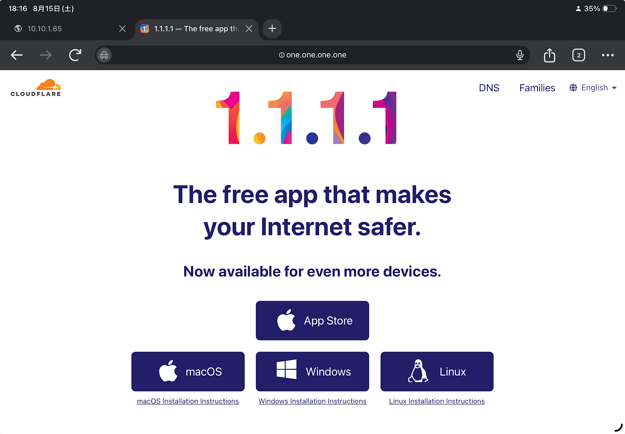
iPadのブラウザから https://1.1.1.1 にアクセスしてみたところ、 https://one.one.one.one にリダイレクトされページが表示されませんでした。
原因は名前解決でした。TCP 443 自体はトンネル経由で繋がっていて(301 が返ってきているのがその証拠)、リダイレクト先の one.one.one.one を、DNS サーバーを持たない閉域の iPad が解決できていません。宛先を IP で許可する方式では、こうして DNS とリダイレクト先が考慮から漏れがちです。
幸い 1.1.1.1 はパブリック DNS リゾルバでもあるので、DHCP で配るリゾルバを 1.1.1.1 に向けます。DNS クエリも許可済みの経路でトンネルを通るようになります。
Router(config)# ip dhcp pool VLAN10
Router(dhcp-config)#  dns-server 1.1.1.1
iPad を繋ぎ直すと one.one.one.one が解決され、ページが表示されました。
経路選択を確認する
同じ宛先への経路が複数あるとき、BGP はベストパス選択という多段審査で使う経路を 1 つに決めます。主要な審査順は次の通りです。
- Local Preference — 大きい方(自 AS 内のポリシー)
- AS_PATH の長さ — 短い方
- Origin・MED などの属性
- すべて同点なら、先に届いていた eBGP 経路
AWS の Site-to-Site VPN はもともとトンネル 2 本構成なので、使っていなかった 2 本目を上げれば「同じ経路が 2 つ届く」状況を作れます。これを使って、審査項目を 1 つずつ手で動かして選択が変わるのを確認していきます(2 本目の設定の流れは 1 本目と同じなので省略します)。
同点なら、先に届いた方が勝つ
2 本目を上げると、同じ経路が 2 経路から届くようになりました。
Router#show ip bgp 10.10.0.0
BGP routing table entry for 10.10.0.0/16, version 6
Paths: (2 available, best #2, table default)
  64512, (received & used)
    169.254.89.69 from 169.254.89.69 (169.254.89.69)      ← Tunnel2
      Origin IGP, metric 100, localpref 100, valid, external
  64512, (received & used)
    169.254.130.197 from 169.254.130.197 (169.254.130.197) ← Tunnel1
      Origin IGP, metric 100, localpref 100, valid, external, best
2 つの経路は AS_PATH(64512)も metric も localpref も完全に同点です。それでも Tunnel1 側に best が付いているのは、判定の最後に「先に届いていた eBGP 経路を優先する」というルールのためです(経路がむやみに切り替わらないようにする安定性のための決まりです)。
AS_PATH 短い経路が優先
AS パスプリペンドを試します。Tunnel1 から受信する経路の AS_PATH に、送信元の AS 番号をわざと水増しして「長い経路」に見せる設定です。
Router(config)# route-map PREPEND-IN permit 10
Router(config-route-map)# set as-path prepend 64512 64512
Router(config-route-map)# router bgp 65001
Router(config-router)# address-family ipv4 unicast
Router(config-router-af)# neighbor 169.254.130.197 route-map PREPEND-IN in
BGP は受信済みの経路を勝手に再評価しないため、clear ip bgp 169.254.130.197 soft in で再受信させます。
Router#show ip bgp 10.10.0.0
BGP routing table entry for 10.10.0.0/16, version 8
Paths: (3 available, best #1, table default)
  64512, (received & used)
    169.254.89.69 from 169.254.89.69 (169.254.89.69)       ← Tunnel2
      Origin IGP, metric 100, localpref 100, valid, external, best
  64512 64512 64512
    169.254.130.197 from 169.254.130.197 (169.254.130.197)  ← Tunnel1(水増し後)
      Origin IGP, metric 100, localpref 100, valid, external
  64512, (received-only)
    169.254.130.197 from 169.254.130.197 (169.254.130.197)  ← Tunnel1(受信した原本)
Tunnel1 の AS_PATH が 64512 64512 64512 に伸び、best が Tunnel2 に移りました(received-only の行は soft-reconfiguration inbound が保管している加工前の原本で、route-map の適用前後を見比べられます)。経路表も確認します。
Router#show ip route 1.1.1.1
Routing entry for 1.1.1.1/32
  Known via "bgp 65001", distance 20, metric 100
  Last update from 169.254.89.69 00:00:22 ago
next-hop が Tunnel2 側に切り替わっています。AS_PATH は短い方が選ばれます。片方の経路をわざと長く見せ、その経路を使わせないよう誘導することで冗長経路の Active/Standby 制御ができます。なお、実運用のプリペンドは広報する側が送信(out)方向に付けて相手の経路選択を誘導するものです。今回は効果を 1 台で完結して観測するため、受信(in)側の route-map で再現しています。
Local Preference — AS_PATH より強い
審査 1 位の Local Preference も動かしてみます。Local Preference は「自分の AS の中で、この経路をどれだけ好むか」という値で、eBGP の相手には伝わらない自 AS 内のポリシーです(デフォルト 100・大きい方が勝ち)。
今度は 1 つの route-map に「AS_PATH を水増しする」と「Local Preference を上げる」を同居させて、わざと審査項目同士を矛盾させてみます。
Router(config)# route-map PREPEND-AND-PREFER permit 10
Router(config-route-map)# set as-path prepend 64512 64512
Router(config-route-map)# set local-preference 200
Router(config-route-map)# router bgp 65001
Router(config-router)# address-family ipv4 unicast
Router(config-router-af)# neighbor 169.254.130.197 route-map PREPEND-AND-PREFER in
適用後、先ほどと同じく clear ip bgp 169.254.130.197 soft in で再受信させてから、選択される経路を確認します。
Router#show ip bgp 10.10.0.0
BGP routing table entry for 10.10.0.0/16, version 10
Paths: (3 available, best #2, table default)
  64512, (received & used)
    169.254.89.69 from 169.254.89.69 (169.254.89.69)       ← Tunnel2
      Origin IGP, metric 100, localpref 100, valid, external
  64512 64512 64512
    169.254.130.197 from 169.254.130.197 (169.254.130.197)  ← Tunnel1
      Origin IGP, metric 100, localpref 200, valid, external, best
  64512, (received-only)
    169.254.130.197 from 169.254.130.197 (169.254.130.197)
      Origin IGP, metric 100, localpref 100, valid, external
Tunnel1 は AS_PATH では 3 対 1 で最長ですがlocalpref 200 で best を取り返しました。
経路選択の各設定は目的に応じて使い分けます。Local Preference は自 AS 内の「内規」で、確実に効きます。AS パスプリペンドや MED は他 AS への「依頼」で、相手のポリシー次第では無視されます。 自分が出す通信の出口は Local Preference で確実に決め、相手から入ってくる通信はプリペンドで誘導します。
最後に
ここまで、タグ VLAN、RTX1200 による router on a stick 構成、そして C841M による AWS との BGP 接続を試してきました。
これまで AWS 認定の ANS やネスペ試験などでなんとなく理解していた内容が、実際に手を動かして構築することで一気に解像度があがりました。
BGP は EC2上やコンテナでソフトウェアのルーターを動かして検証も可能でしたが、やはり実機にLANケーブルを接続して挙動を確認する体験は大きな学びになりました。
また実機を用いたハンズオン資料を AI に用意してもらうことで、各ベンダーのコマンドリファレンスなどを調べることなく最短キャッチアップできました。
中古の業務用ルーターは数千円で調達可能です。
オンプレミス側の機器設定に興味のある方は是非試してみてはいかがでしょうか。
この記事が誰かの役に立つと幸いです。以上。リテールアプリ共創部のきんじょーでした。